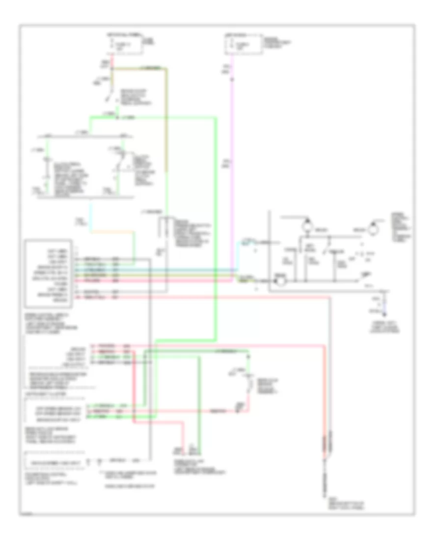
CRUISE CONTROL
4.9L
4.9L, Cruise Control Wiring Diagram for Ford Cab & Chassis F350 1996

List of elements for 4.9L, Cruise Control Wiring Diagram for Ford Cab & Chassis F350 1996:
- (behind bottom of right cowl panel)
- (behind left side of instrument panel, taped to main harness near steering column)
- (behind left side of instrument panel)
- (left rear of engine compartment,on bracket)
- (left side of engine compartment, near brake master cylinder)
- (left side of safety wall)
- (not used)
- (on axle assembly)
- (on brake/ clutch
- (right side of instrument panel, behind glove box)
- 15a
- A/t
- Accel
- Brake on/off (boo) switch (on brake pedal support)
- Brake on/off in
- Brake on/off sw input
- Brake press in
- Brake pressure switch (near left front frame rail) (opens when brake system is pressurized)
- Brush
- Clutch pedal position switch
- Clutch pedal position switch jumper
- Coast
- Diff speed sensor high
- Diff speed sensor low
- Engine compartment fuse box
- Fuse 13
- Fuse 5 15a
- Fuse panel
- G203
- Gasoline over 8500 gvwr
- Gasoline under 8500 gvwr and all diesel
- Ground
- Horn
- Horns, anti- theft & door locks systems
- Hot at all times
- Hot in run
- Instrument cluster
- M/t
- Nca
- Off
- Ohms
- Pedal support)
- Pnk
- Power
- Powertrain control module (pcm)
- Programmable speedometer/ odometer module (psom)
- Rabs data link connector
- Rear anti-lock brake (rabs) module
- Rear axle sensor
- Red
- Red/
- Red/ pnk
- Red/pnk
- Resume
- Set/
- Spd ctrl sw rtrn
- Speed control servo/ amplifier assembly
- Speed control/ horn switch assembly (in steering wheel)
- Speed ctrl sw in
- Tan/
- Vehicle speed (vss) input
- Vss input
- Vss output
5.8L
5.8L, Cruise Control Wiring Diagram for Ford Cab & Chassis F350 1996
List of elements for 5.8L, Cruise Control Wiring Diagram for Ford Cab & Chassis F350 1996:
- (behind bottom of right cowl panel)
- (behind left side of instrument panel, taped to main harness near steering column)
- (behind left side of instrument panel)
- (left rear of engine compartment,on bracket)
- (left side of engine compartment, near brake master cylinder)
- (left side of safety wall)
- (not used)
- (on axle assembly)
- (on brake/ clutch
- (right side of instrument panel, behind glove box)
- 15a
- A/t
- Accel
- Brake on/off (boo) switch (on brake pedal support)
- Brake on/off in
- Brake on/off sw input
- Brake press in
- Brake pressure switch (near left front frame rail) (opens when brake system is pressurized)
- Brush
- Clutch pedal position switch
- Clutch pedal position switch jumper
- Coast
- Diff speed sensor high
- Diff speed sensor low
- Engine compartment fuse box
- Fuse 13
- Fuse 5 15a
- Fuse panel
- G203
- Gasoline over 8500 gvwr
- Gasoline under 8500 gvwr and all diesel
- Ground
- Horn
- Horns, anti- theft & door locks systems
- Hot at all times
- Hot in run
- Instrument cluster
- M/t
- Nca
- Off
- Ohms
- Pedal support)
- Pnk
- Power
- Powertrain control module (pcm)
- Programmable speedometer/ odometer module (psom)
- Rabs data link connector
- Rear anti-lock brake (rabs) module
- Rear axle sensor
- Red
- Red/
- Red/ pnk
- Red/pnk
- Resume
- Set/
- Spd ctrl sw rtrn
- Speed control servo/ amplifier assembly
- Speed control/ horn switch assembly (in steering wheel)
- Speed ctrl sw in
- Tan/
- Vehicle speed (vss) input
- Vss input
- Vss output
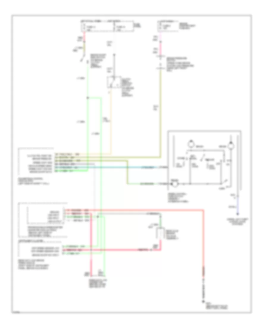
7.3L
7.3L DI Turbo Diesel, Cruise Control Wiring Diagram for Ford Cab & Chassis F350 1996
List of elements for 7.3L DI Turbo Diesel, Cruise Control Wiring Diagram for Ford Cab & Chassis F350 1996:
- (behind left side of instrument panel)
- (left side of safety wall)
- (on axle assembly)
- (on brake/ clutch
- (on brake/ clutch pedal support)
- (right side of instrument panel, behind glove box)
- 10a
- 15a
- 29
- Accel
- Brake on/off (boo) switch
- Brake on/off sw in
- Brake on/off sw input
- Brake press sw
- Brake pressure switch (opens when brake
- Brush
- Clutch pedal position switch
- Clutch pdl posit sw
- Coast
- Diff speed sensor high
- Diff speed sensor low
- Engine compartment fuse box
- Fuse 13
- Fuse 18
- Fuse 5 15a
- Fuse panel
- G203 (behind bottom of right cowl panel)
- Ground
- Horn
- Horns, anti-theft & door locks systems
- Hot at all times
- Hot in run
- Instrument cluster
- Nca
- Off
- Ohms
- Pedal support)
- Pnk
- Powertrain control module (pcm)
- Programmable speedometer/ odometer module (psom)
- Rabs data link connector (behind lower center of i/p)
- Rear anti-lock brake (rabs) module
- Rear axle sensor
- Red
- Red/
- Red/ pnk
- Red/pnk
- Resume
- Set/
- Speed cont com sig
- Speed cont gnd
- Speed control/ horn switch assembly (steering wheel)
- System has pressure) (near left front rail)
- Tan/
- Vehicle speed sens
- Vss input
- Vss output
7.5L
7.5L, Cruise Control Wiring Diagram for Ford Cab & Chassis F350 1996
List of elements for 7.5L, Cruise Control Wiring Diagram for Ford Cab & Chassis F350 1996:
- (behind bottom of right cowl panel)
- (behind left side of instrument panel, taped to main harness near steering column)
- (behind left side of instrument panel)
- (left rear of engine compartment,on bracket)
- (left side of engine compartment, near brake master cylinder)
- (left side of safety wall)
- (not used)
- (on axle assembly)
- (on brake/ clutch
- (right side of instrument panel, behind glove box)
- 15a
- A/t
- Accel
- Brake on/off (boo) switch (on brake pedal support)
- Brake on/off in
- Brake on/off sw input
- Brake press in
- Brake pressure switch (near left front frame rail) (opens when brake system is pressurized)
- Brush
- Clutch pedal position switch
- Clutch pedal position switch jumper
- Coast
- Diff speed sensor high
- Diff speed sensor low
- Engine compartment fuse box
- Fuse 13
- Fuse 5 15a
- Fuse panel
- G203
- Gasoline over 8500 gvwr
- Gasoline under 8500 gvwr and all diesel
- Ground
- Horn
- Horns, anti- theft & door locks systems
- Hot at all times
- Hot in run
- Instrument cluster
- M/t
- Nca
- Off
- Ohms
- Pedal support)
- Pnk
- Power
- Powertrain control module (pcm)
- Programmable speedometer/ odometer module (psom)
- Rabs data link connector
- Rear anti-lock brake (rabs) module
- Rear axle sensor
- Red
- Red/
- Red/ pnk
- Red/pnk
- Resume
- Set/
- Spd ctrl sw rtrn
- Speed control servo/ amplifier assembly
- Speed control/ horn switch assembly (in steering wheel)
- Speed ctrl sw in
- Tan/
- Vehicle speed (vss) input
- Vss input
- Vss output