ANTI-THEFT
Forced Entry Wiring Diagram for Volvo V70 R 2004

List of elements for Forced Entry Wiring Diagram for Volvo V70 R 2004:
- (in left side rear window)
- (in right side rear window)
- A11
- A12
- A13
- A14
- A15
- A16
- Air conditioning system
- Alarm siren (at inside front of front right wheelwell)
- B12
- B17
- B18
- C18
- Central electronic module
- Climate control module
- Combination instrument panel dim
- Computer data lines system
- D20
- Front mass movement sensor (center of roof)
- Fuse c38 5a
- G47 (at left rear of passenger's compartment, near floor)
- G66 (below driver's seat, near rocker panel)
- G67 (below passenger's seat, near rocker panel)
- G72 (at left rear of passenger's compartment, near floor)
- G93 (at rear of left fender)
- G94 (at rear of right fender)
- G98 (at front center of headliner)
- G99 (above left rear window)
- Hood alarm contact (at left front of engine compt)
- Hot at all times
- Inclination sensor module (left rear corner of cargo compartment)
- Key
- Left front door control module
- Left front door lock unit
- Left glass breakage sensor (optional)
- Left rear door lock unit
- Nca
- Passenger compartment relay/fuse box (at left end of dash)
- Pnk
- Rear electronic module (at left rear corner of cargo compartment, on cargo compartment relay/fuse box)
- Red
- Reduced alarm switch
- Right front door control module
- Right front door lock unit
- Right glass breakage sensor (optional)
- Right rear door lock unit
- Solar sensor, indicator alarm & electronic immobilizer (on top center of dash)
- Tailgate glass breakage sensor (optional) (in tailgate window)
- Trunk lid lock unit
- Ulk
- Upper electronic module (above center of windshield)
- W/ subwoofer
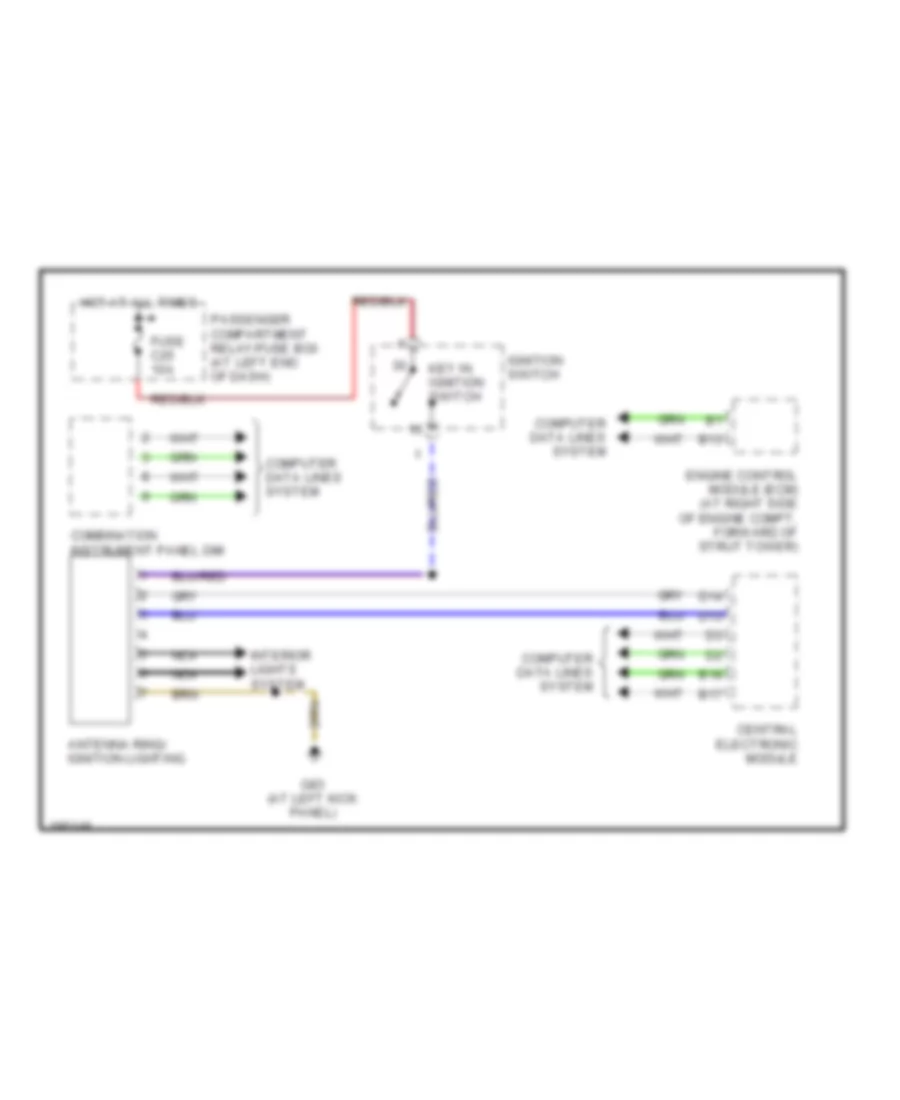
Immobilizer Wiring Diagram for Volvo V70 R 2004
List of elements for Immobilizer Wiring Diagram for Volvo V70 R 2004:
- Antenna ring/ ignition lighting
- B13
- B17
- B18
- Central electronic module
- Combination instrument panel dim
- Computer data lines system
- D13
- D14
- Engine control module (ecm) (at right side of engine compt, forward of strut tower)
- Fuse c25 10a
- G83 (at left kick panel)
- Hot at all times
- Ignition switch
- Interior lights system
- Key in ignition switch
- Nca
- Passenger compartment relay/fuse box (at left end of dash)