AIR CONDITIONING
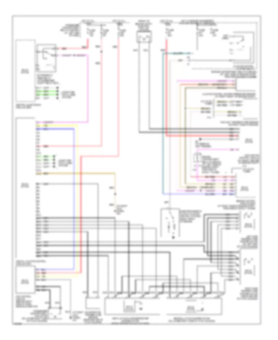
Automatic A/C Wiring Diagram (1 of 2) for Volvo V70 R 2004

List of elements for Automatic A/C Wiring Diagram (1 of 2) for Volvo V70 R 2004:
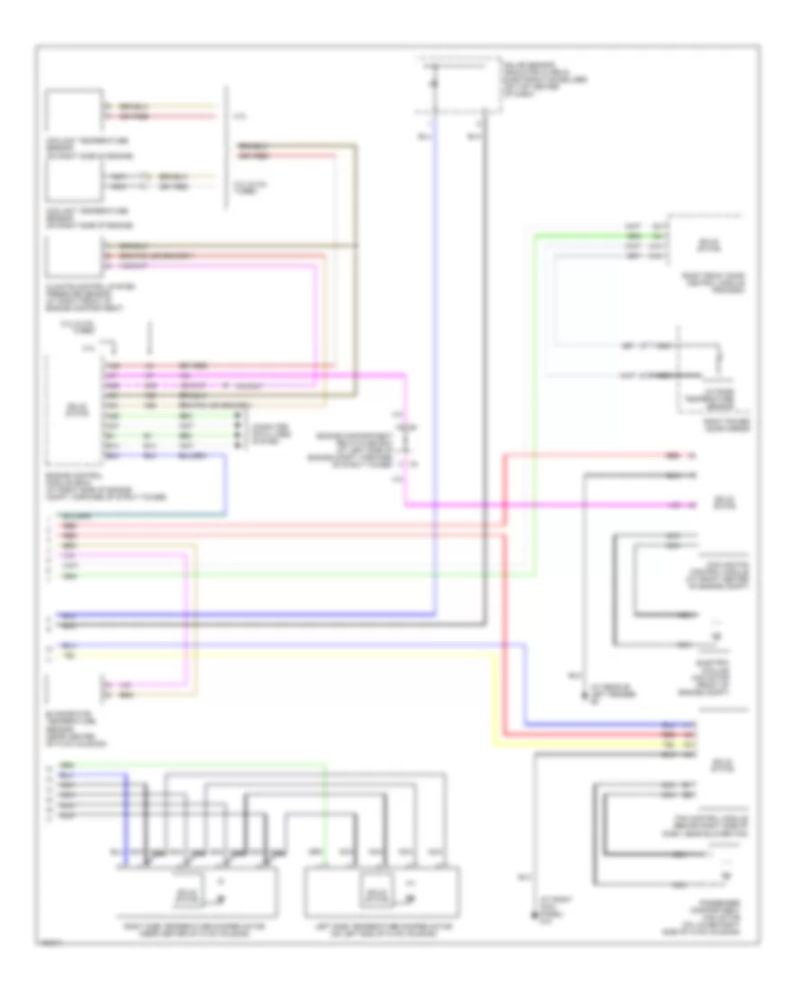
Automatic A/C Wiring Diagram (2 of 2) for Volvo V70 R 2004
List of elements for Automatic A/C Wiring Diagram (2 of 2) for Volvo V70 R 2004:
Manual A/C Wiring Diagram for Volvo V70 R 2004
List of elements for Manual A/C Wiring Diagram for Volvo V70 R 2004: