ENGINE PERFORMANCE
2.3L TURBO
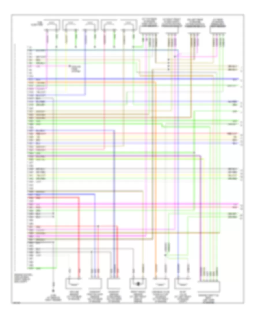
2.3L Turbo, Engine Performance Wiring Diagram (1 of 3) for Volvo V70 R 2004

List of elements for 2.3L Turbo, Engine Performance Wiring Diagram (1 of 3) for Volvo V70 R 2004:
- (on left front eng compt) intake manifold temperature sensor
- (on lower left front of engine) oil level sensor
- (on top rear of engine) mass airflow (maf) sensor
- (right front of eng compt) climate control system pressure sensor
- 31/96 (at rear of right fender)
- A10
- A11
- A12
- A13
- A14
- A15
- A16
- A17
- A18
- A19
- A20
- A21
- A22
- A23
- A24
- A25
- A26
- A27
- A28
- A29
- A30
- A31
- A32
- A33
- A34
- A35
- A36
- A37
- A38
- A39
- A40
- A41
- A42
- A43
- A44
- A45
- A46
- A47
- A48
- A49
- A50
- A51
- A52
- A53
- A54
- A55
- A56
- A57
- A58
- A59
- A60
- A61
- A62
- A63
- A64
- A65
- A66
- A67
- A68
- A69
- A70
- Camshaft position sensor (top rear of engine)
- Camshaft sensor (if equipped) (top rear of engine)
- Computer data lines system
- Cooling fans system
- Engine control module (right side of engine compt, forward of strut tower)
- Engine throttle body (left side of engine)
- Evap valve (left front of eng compt)
- Front knock sensor (top left front of eng)
- Fuel injectors
- Impulse sensor (top rear of engine)
- Nac
- Nca
- Pnk
- Rear knock sensor (top left rear of engine)
- Red
- Variable valve timing inlet solenoid (at top rear of engine)
- Variable valve timing outlet solenoid (at top front of engine)
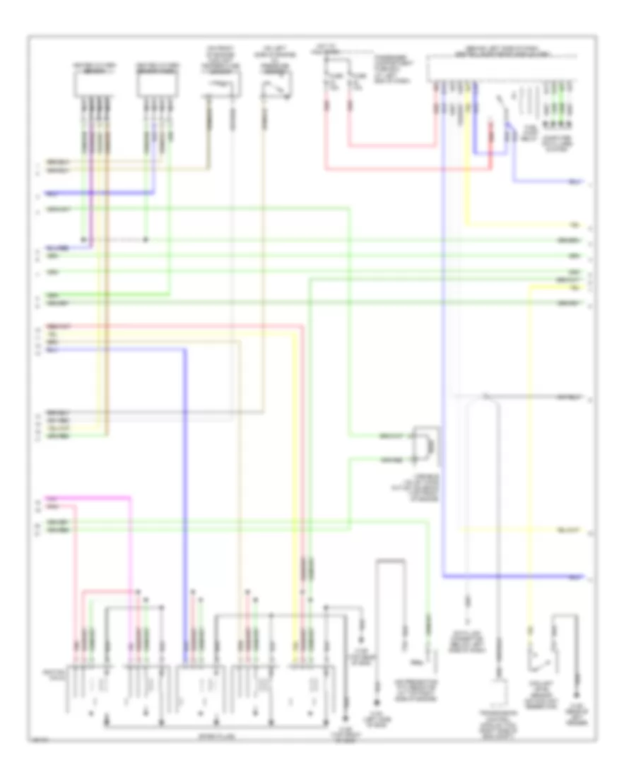
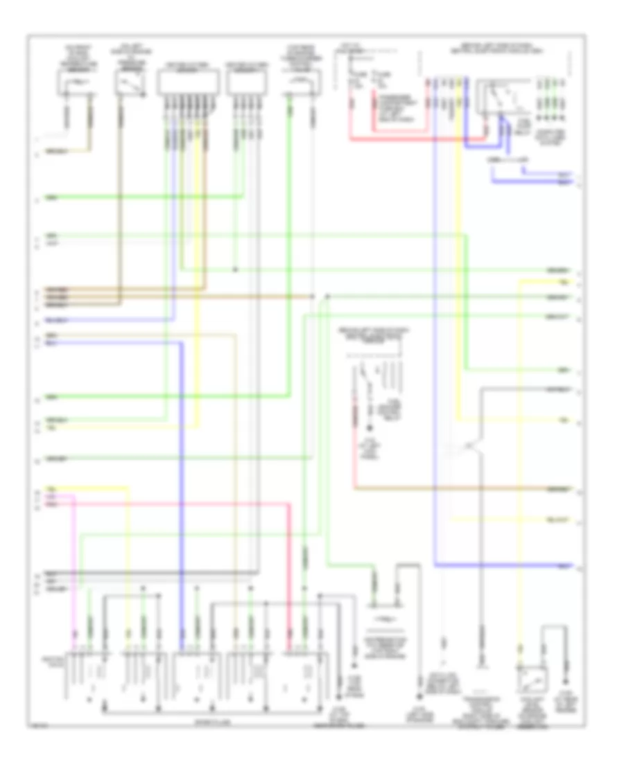
2.3L Turbo, Engine Performance Wiring Diagram (2 of 3) for Volvo V70 R 2004
List of elements for 2.3L Turbo, Engine Performance Wiring Diagram (2 of 3) for Volvo V70 R 2004:
- (behind left side of dash) central electronic module
- (behind left side of dash) central electronic module (cem)
- (on front of eng) coolant temperature sensor
- (on left side of engine) oil pressure sensor
- (top rear of engine) turbocharger control valve
- 31/6 (at left kick panel)
- 31/88 (at top of eng, near spark plugs)
- 31/89 (top rear of eng)
- 31/91 (left side of engine)
- 31/93 (at rear of left fender)
- A20
- Air preheating ptc resistor (top right side of engine)
- B14
- B17
- B18
- B22
- C14
- Computer data lines system
- Coolant level sensor (on engine coolant reservoir)
- Data link connector (below left side of dash)
- Fuel leakage control relay
- Fuel pump relay
- Fuse 10a
- Fuse 15a
- Heated oxygen sensor
- Heated oxygen sensor 1
- Hot at all times
- Ignition coils
- Nca
- Passenger compartment fuse box (at left end of dash)
- Pnk
- Red
- Spark plugs
- Transmission control module (right side of eng compt, forward of strut tower)
- V70
- V70r
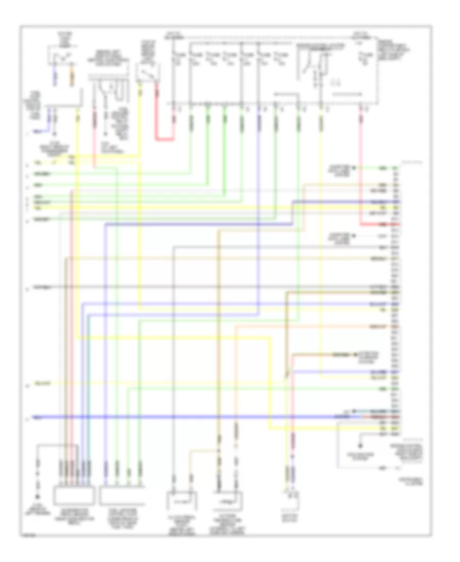
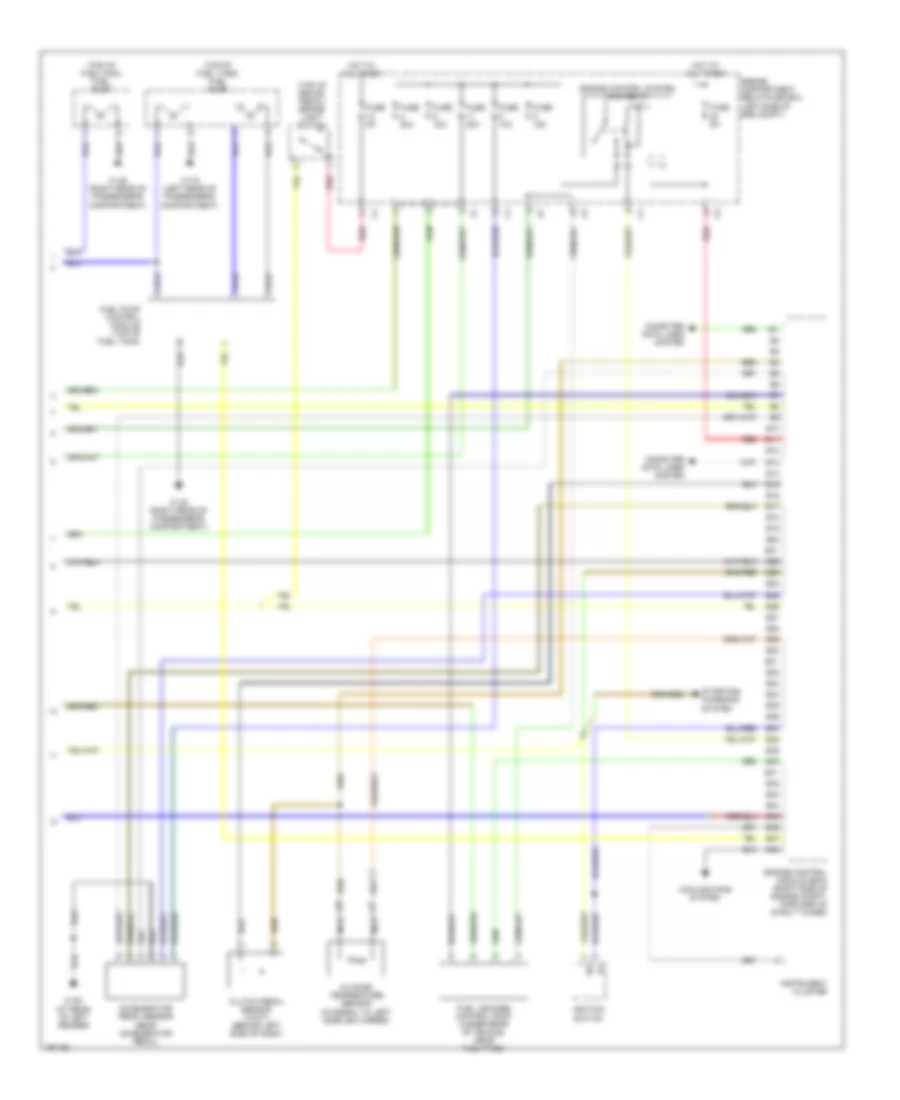
2.3L Turbo, Engine Performance Wiring Diagram (3 of 3) for Volvo V70 R 2004
List of elements for 2.3L Turbo, Engine Performance Wiring Diagram (3 of 3) for Volvo V70 R 2004:
- (top of brake pedal) brake light switch
- (top of fuel tank) fuel pump
- (top of fueltank) fuel pump
- 31/48 (right rear of passenger's compartment)
- 31/72 (left rear of passenger's compartment)
- 31/93 (at rear of left fender)
- Accelerator pedal sensor (near accelerator pedal)
- B10
- B11
- B12
- B13
- B14
- B15
- B16
- B17
- B18
- B19
- B20
- B21
- B22
- B23
- B24
- B25
- B26
- B27
- B28
- B29
- B30
- B31
- B32
- B33
- B34
- B35
- B36
- B37
- B38
- B39
- B40
- B41
- B42
- B43
- B44
- B45
- B46
- B47
- B48
- Clutch pedal sensor (w/m/t) (behind left side of dash)
- Computer data lines system
- Cooling fans system
- Engine compartment relay/fuse box (left side of eng compt)
- Engine control module (ecm) (right side of engine compt, forward of strut tower)
- Engine control system main relay
- Fuel leakage control pump (under rear of vehicle, near fuel tank)
- Fuel pump control module (top of fuel tank)
- Fuse 10a
- Fuse 15a
- Fuse 20a
- Fuse 5a
- Hot at all times
- Ignition switch
- Instrument cluster
- Nca
- Outside temperature sensor (integral to left sideview mirror)
- Red
- Starting/ charging system
2.4L
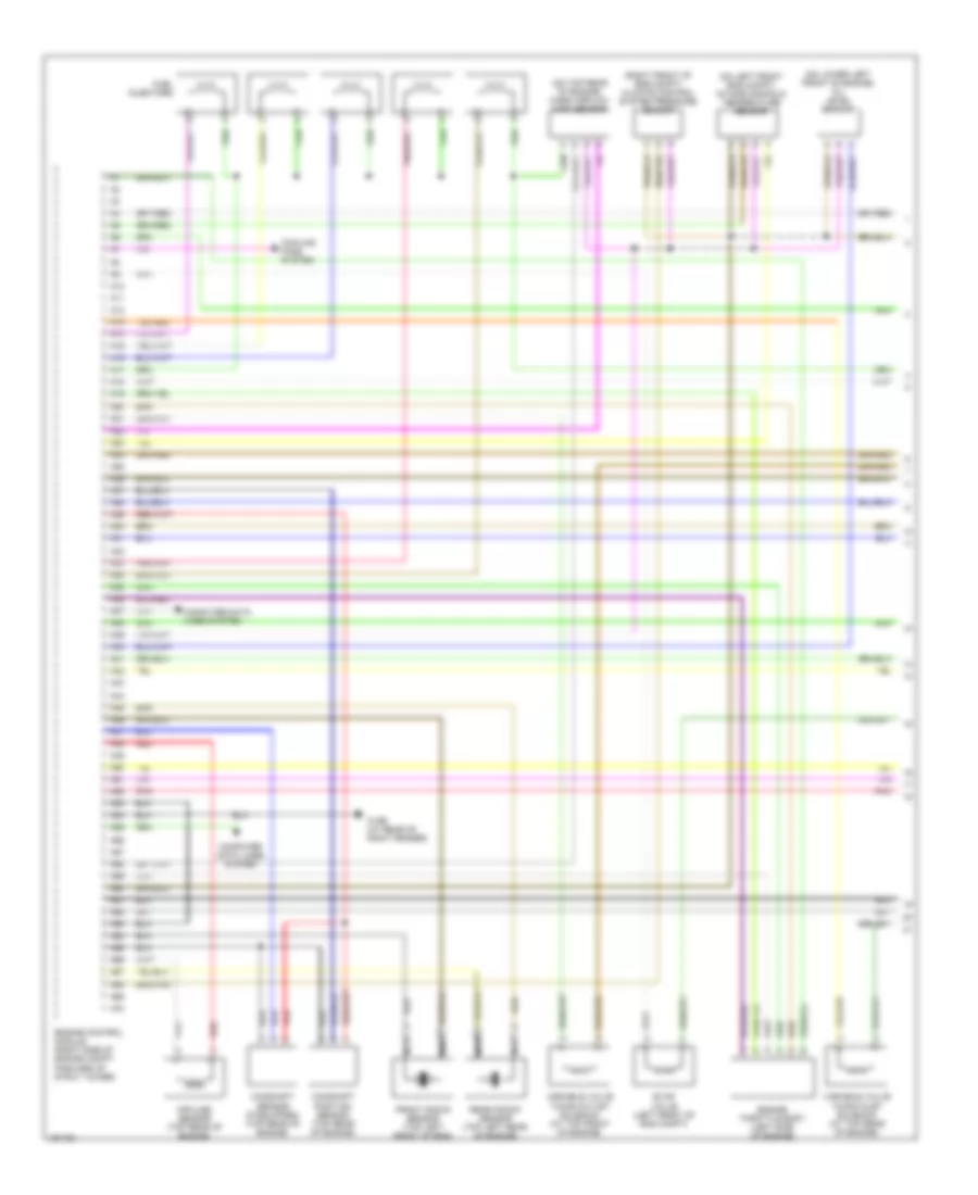
2.4L, Engine Performance Wiring Diagram (1 of 3) for Volvo V70 R 2004
List of elements for 2.4L, Engine Performance Wiring Diagram (1 of 3) for Volvo V70 R 2004:
- (at rear of engine) pressure & temp sensor
- (at right front of eng compt) climate control pressure sensor
- (at top rear of engine) mass airflow (maf) sensor
- (on left rear of engine) intake manifold pressure sensor
- 31/96 (at rear of right fender)
- A10
- A11
- A12
- A13
- A14
- A15
- A16
- A17
- A18
- A19
- A20
- A21
- A22
- A23
- A24
- A25
- A26
- A27
- A28
- A29
- A30
- A31
- A32
- A33
- A34
- A35
- A36
- A37
- A38
- A39
- A40
- A41
- A42
- A43
- A44
- A45
- A46
- A47
- A48
- A49
- A50
- A51
- A52
- A53
- A54
- A55
- A56
- A57
- A58
- A59
- A60
- A61
- A62
- A63
- A64
- A65
- A66
- A67
- A68
- A69
- A70
- Camshaft position (cmp) sensor (on top rear of engine)
- Camshaft sensor (if equipped) (on top rear of engine)
- Cooling fans system
- Engine control module (ecm) (right side of eng compt)
- Engine throttle body (left side of engine)
- Evap valve (at left front of engine compt)
- Front knock sensor (at left front side of engine)
- Fuel injectors
- Impulse sensor (at top rear of engine)
- Pnk
- Red
- Variable valve timing outlet solenoid (at top front of engine)
2.4L, Engine Performance Wiring Diagram (2 of 3) for Volvo V70 R 2004
List of elements for 2.4L, Engine Performance Wiring Diagram (2 of 3) for Volvo V70 R 2004:
- (behind left side of dash) central electronic module (cem)
- (on front of engine) coolant temperature sensor
- (on left side of engine) oil pressure sensor
- 31/88 (top front of eng)
- 31/89 (top rear of eng)
- 31/91 (left side of eng)
- 31/93 (rear of left fender)
- A20
- Air preheating ptc resistor (at top right side of engine)
- B14
- B17
- B18
- B22
- C14
- Computer data lines system
- Coolant level sensor (on coolant reservoir)
- Data link connector (below left side of dash)
- Fuel pump relay
- Fuse 10a
- Fuse 15a
- Heated oxygen sensor
- Heated oxygen sensor (ho2s) 1
- Hot at all times
- Ignition coils
- Nca
- Passenger compartment fuse box (at left end of dash)
- Pnk
- Red
- Spark plugs
- Transmission control module (tcm) (right side of eng compt)
- Variable valve timing outlet solenoid (top front of engine)
2.4L, Engine Performance Wiring Diagram (3 of 3) for Volvo V70 R 2004
List of elements for 2.4L, Engine Performance Wiring Diagram (3 of 3) for Volvo V70 R 2004:
- (behind left side of dash) central electronic module (cem)
- (in fuel tank) fuel pump
- (top of brake pedal) brake light switch
- 31/48 (right rear of passenger's compt)
- 31/6 (at left kick panel)
- 31/93 (rear of left fender)
- A/c system
- Accelerator pedal sensor (near accelerator pedal)
- B10
- B11
- B12
- B13
- B14
- B15
- B16
- B17
- B18
- B19
- B20
- B21
- B22
- B23
- B24
- B25
- B26
- B27
- B28
- B29
- B30
- B31
- B32
- B33
- B34
- B35
- B36
- B37
- B38
- B39
- B40
- B41
- B42
- B43
- B44
- B45
- B46
- B47
- B48
- Clutch pedal sensor (w/m/t) (behind left side of dash)
- Computer data lines system
- Cooling fans system
- Engine compartment relay/fuse box (left side of eng compt)
- Engine control module (ecm) (right side of eng compt)
- Engine control system main relay
- Fuel leakage control pump (under rear of vehicle, near fuel tank)
- Fuel leakage control relay (on pass compt relay box)
- Fuel pump control module (top of fuel tank)
- Fuse 10a
- Fuse 15a
- Fuse 20a
- Fuse 5a
- Hot at all times
- Ignition switch
- Instrument cluster
- Nca
- Outside temperature sensor (integral to left sideview mirror)
- Red
- Starting/ charging system
2.5L TURBO
2.5L Turbo, Engine Performance Wiring Diagram (1 of 3) for Volvo V70 R 2004
List of elements for 2.5L Turbo, Engine Performance Wiring Diagram (1 of 3) for Volvo V70 R 2004:
- (on left front eng compt) intake manifold temperature sensor
- (on lower left front of engine) oil level sensor
- (on top rear of engine) mass airflow (maf) sensor
- (right front of eng compt) climate control system pressure sensor
- 31/96 (at rear of right fender)
- A10
- A11
- A12
- A13
- A14
- A15
- A16
- A17
- A18
- A19
- A20
- A21
- A22
- A23
- A24
- A25
- A26
- A27
- A28
- A29
- A30
- A31
- A32
- A33
- A34
- A35
- A36
- A37
- A38
- A39
- A40
- A41
- A42
- A43
- A44
- A45
- A46
- A47
- A48
- A49
- A50
- A51
- A52
- A53
- A54
- A55
- A56
- A57
- A58
- A59
- A60
- A61
- A62
- A63
- A64
- A65
- A66
- A67
- A68
- A69
- A70
- Camshaft position sensor (top rear of engine)
- Camshaft sensor (if equipped) (top rear of engine)
- Computer data lines system
- Cooling fans system
- Engine control module (right side of engine compt, forward of strut tower)
- Engine throttle body (left side of engine)
- Evap valve (left front of eng compt)
- Front knock sensor (top left front of eng)
- Fuel injectors
- Impulse sensor (top rear of engine)
- Nac
- Nca
- Pnk
- Rear knock sensor (top left rear of engine)
- Red
- Variable valve timing inlet solenoid (at top rear of engine)
- Variable valve timing outlet solenoid (at top front of engine)
2.5L Turbo, Engine Performance Wiring Diagram (2 of 3) for Volvo V70 R 2004
List of elements for 2.5L Turbo, Engine Performance Wiring Diagram (2 of 3) for Volvo V70 R 2004:
- (behind left side of dash) central electronic module
- (behind left side of dash) central electronic module (cem)
- (on front of eng) coolant temperature sensor
- (on left side of engine) oil pressure sensor
- (top rear of engine) turbocharger control valve
- 31/6 (at left kick panel)
- 31/88 (at top of eng, near spark plugs)
- 31/89 (top rear of eng)
- 31/91 (left side of engine)
- 31/93 (at rear of left fender)
- A20
- Air preheating ptc resistor (top right side of engine)
- B14
- B17
- B18
- B22
- C14
- Computer data lines system
- Coolant level sensor (on engine coolant reservoir)
- Data link connector (below left side of dash)
- Fuel leakage control relay
- Fuel pump relay
- Fuse 10a
- Fuse 15a
- Heated oxygen sensor
- Heated oxygen sensor 1
- Hot at all times
- Ignition coils
- Nca
- Passenger compartment fuse box (at left end of dash)
- Pnk
- Red
- Spark plugs
- Transmission control module (right side of eng compt, forward of strut tower)
- V70
- V70r
2.5L Turbo, Engine Performance Wiring Diagram (3 of 3) for Volvo V70 R 2004
List of elements for 2.5L Turbo, Engine Performance Wiring Diagram (3 of 3) for Volvo V70 R 2004:
- (top of brake pedal) brake light switch
- (top of fuel tank) fuel pump
- (top of fueltank) fuel pump
- 31/48 (right rear of passenger's compartment)
- 31/72 (left rear of passenger's compartment)
- 31/93 (at rear of left fender)
- Accelerator pedal sensor (near accelerator pedal)
- B10
- B11
- B12
- B13
- B14
- B15
- B16
- B17
- B18
- B19
- B20
- B21
- B22
- B23
- B24
- B25
- B26
- B27
- B28
- B29
- B30
- B31
- B32
- B33
- B34
- B35
- B36
- B37
- B38
- B39
- B40
- B41
- B42
- B43
- B44
- B45
- B46
- B47
- B48
- Clutch pedal sensor (w/m/t) (behind left side of dash)
- Computer data lines system
- Cooling fans system
- Engine compartment relay/fuse box (left side of eng compt)
- Engine control module (ecm) (right side of engine compt, forward of strut tower)
- Engine control system main relay
- Fuel leakage control pump (under rear of vehicle, near fuel tank)
- Fuel pump control module (top of fuel tank)
- Fuse 10a
- Fuse 15a
- Fuse 20a
- Fuse 5a
- Hot at all times
- Ignition switch
- Instrument cluster
- Nca
- Outside temperature sensor (integral to left sideview mirror)
- Red
- Starting/ charging system