ANTI-LOCK BRAKES
Anti-lock Brakes Wiring Diagram, with Dynamic Stability Control for Volvo V70 R 2004

List of elements for Anti-lock Brakes Wiring Diagram, with Dynamic Stability Control for Volvo V70 R 2004:
- (at front of engine compt) vacuum pump switch
- (left side of engine compt) dstc activation module
- A11
- A12
- A13
- A14
- A37
- A55
- Abs pump motor
- B13
- B17
- B18
- B26
- Brake control module (at left rear corner of engine compt)
- Brake light contact (at top of brake pedal)
- Brake pedal sensor (at left rear corner of engine compt)
- Brake pressure sensor 1 (on brake master cylinder)
- Brake pressure sensor 2 (on brake master cylinder)
- Central electronic module
- Climate control module
- Combined instrument panel dim
- Computer data lines system
- Contact reel
- D12
- Dstc sensor module (under right front seat)
- Engine compartment relay/fuse box (at left side of engine compt)
- Engine control module (at right side of engine compt, forward of strut tower)
- Fuse b12 5a
- Fuse b14 30a
- Fuse b19 30a
- Fuse c23 5a
- Fuse c5 5a
- Fuse c9 5a
- G84 (at right kick panel)
- G93 (at rear of left fender)
- G95 (at rear of left fender)
- Hot at all times
- Hot in on or start
- Left front abs sensor (behind left front wheel, on spindle/ hub assembly)
- Left rear abs sensor (behind left rear wheel, on spindle/ hub assembly)
- Nca
- Passenger compartment relay/fuse box (at left end of dash)
- Pnk
- Red
- Right front abs sensor (behind right front wheel, on spindle/ hub assembly)
- Right rear abs sensor (behind right rear wheel, on spindle/ hub assembly)
- Spin control switch
- Steering angle sensor module (on side of passenger compt relay box)
- Steering wheel module (swm)
- Vacuum pump (at left front of engine)
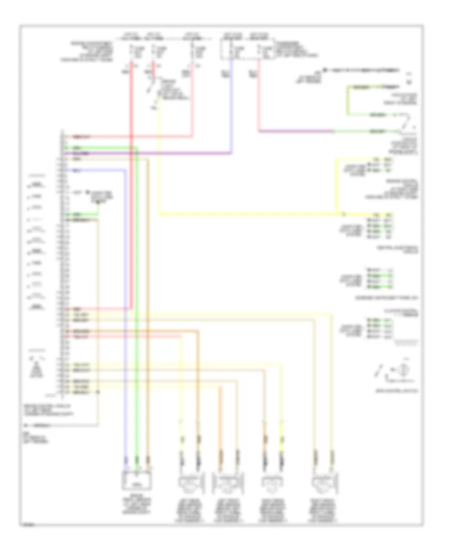
Anti-lock Brakes Wiring Diagram, without Dynamic Stability Control for Volvo V70 R 2004
List of elements for Anti-lock Brakes Wiring Diagram, without Dynamic Stability Control for Volvo V70 R 2004:
- A11
- A12
- A13
- A14
- Abs pump motor
- B13
- B17
- B18
- B26
- Brake control module (at left rear corner of engine compt)
- Brake light contact (at top of brake pedal)
- Brake pedal sensor (at left rear corner of engine compt)
- Central electronic module
- Climate control module
- Combined instrument panel dim
- Computer data lines system
- Engine compartment relay/fuse box (at left side of engine compt, forward of strut tower)
- Engine control module (at right side of engine compt, forward of strut tower)
- Fuse b12 5a
- Fuse b14 30a
- Fuse b19 30a
- Fuse c5 15a
- Fuse c9 5a
- G93 (at rear of left fender)
- G95 (at rear of left fender)
- Hot at all times
- Hot in on or start
- Left front abs sensor (behind left front wheel, on spindle/ hub assembly)
- Left rear abs sensor (behind left rear wheel, on spindle/ hub assembly)
- Nca
- Passenger compartment relay/fuse box (at left end of dash)
- Red
- Right front abs sensor (behind right front wheel, on spindle/ hub assembly)
- Right rear abs sensor (behind right rear wheel, on spindle/ hub assembly)
- Spin control switch
- Vacuum pump (at left front of engine)
- Vacuum pump switch (at front of engine compt)