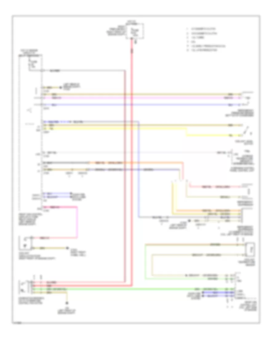
COOLING FAN
Cooling Fan Wiring Diagram for Mercedes-Benz SLK250 2014
List of elements for Cooling Fan Wiring Diagram for Mercedes-Benz SLK250 2014:
- (left rear of engine compt) w16/5
- 1.8l early production & 3.5l
- 1.8l late production
- 1.8l turbo
- 3.5l
- C13d
- C14m
- C18m
- C20m
- C21m
- C2i
- C3m
- Can-c h
- Can-c l
- Combustion engine & a/c w/ integrated control fan motor
- Computer data lines system
- Coolant circulation pump (right front of engine compt)
- Coolant level switch
- Coolant temperature sensor
- Front prefuse box (right front of engine compt)
- Front sam control module w/ fuse/ relay module (left rear of engine compt)
- Fuse 100a
- Fuse 15a
- Hot at all times
- Hot w/ engine circuit 87 relay energized
- Interior temperature sensor w/ integrated fan
- Lin2
- Lues
- Me-sfi (me) control unit (3.5l: left side of engine)
- Mr1
- Overhead control panel control unit
- Red
- Refrigerant compressor
- Refrigerant compressor w/ magnetic clutch (3.5l: left front of engine)
- Refrigerant pressure sensor (bottom of condenser)
- Sig
- Tem
- W/ magnetic clutch
- W/o magnetic clutch
- W16/4 (right front wheel well)
- W16/5 (left rear of engine compt)
- W9 (left front of engine compt)
- X25/2-c2
- X26-c1
- X26/21-c1
 English