
HORN
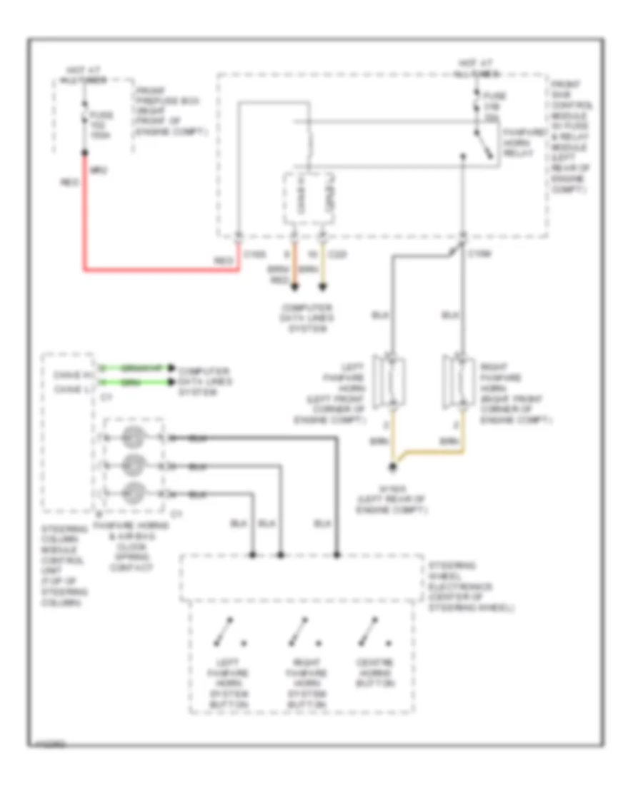
Horn Wiring Diagram for Mercedes-Benz SLK250 2014
List of elements for Horn Wiring Diagram for Mercedes-Benz SLK250 2014:
AIR CONDITIONINGANTI-THEFTCRUISE CONTROLBODY CONTROL MODULESDEFOGGERSCOOLING FANELECTRONIC POWER STEERINGANTI-LOCK BRAKESCOMPUTER DATA LINESENGINE PERFORMANCEELECTRONIC SUSPENSIONEXTERIOR LIGHTSHEADLIGHTSHORNGROUND DISTRIBUTIONINTERIOR LIGHTSMEMORY SYSTEMSINSTRUMENT CLUSTERPOWER DOOR LOCKSRADIOPOWER SEATSNAVIGATIONPOWER WINDOWSPOWER TOP/SUNROOFPOWER MIRRORSPOWER DISTRIBUTIONSTARTING/CHARGINGSUPPLEMENTAL RESTRAINTSTRANSMISSIONWARNING SYSTEMSSHIFT INTERLOCKTRUNK, TAILGATE, FUEL DOORWIPER/WASHER