ENGINE PERFORMANCE
1.8L TURBO
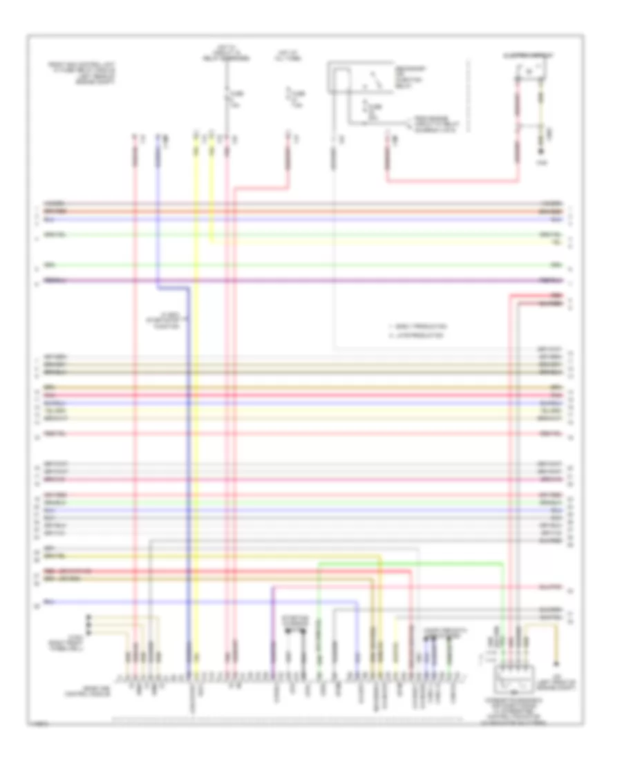
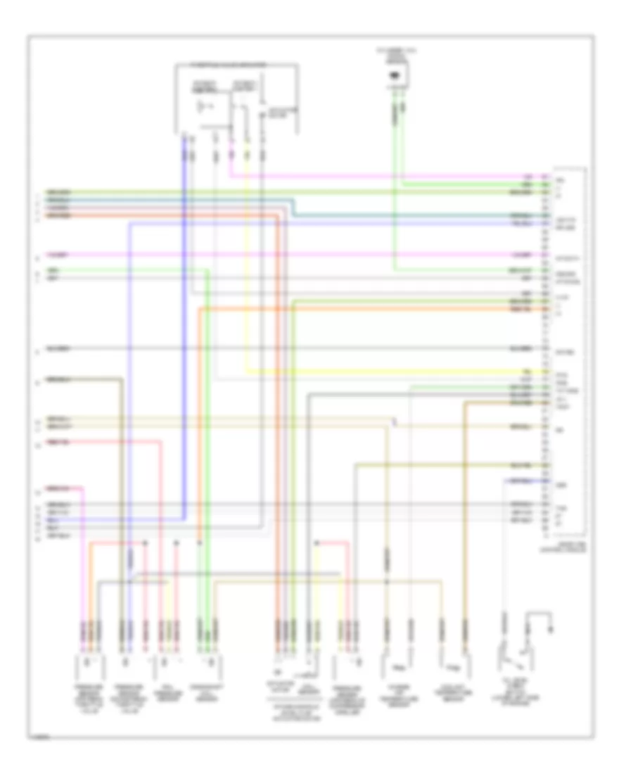
1.8L Turbo, Engine Performance Wiring Diagram (1 of 6) for Mercedes-Benz SLK250 2014

List of elements for 1.8L Turbo, Engine Performance Wiring Diagram (1 of 6) for Mercedes-Benz SLK250 2014:
- (+)
- (-)
- A-wgv
- At zue1
- At zue2
- At zue3
- At zue4
- Cylinder 1 fuel injector
- Cylinder 2 fuel injector
- Cylinder 3 & 4 knock sensor
- Cylinder 3 fuel injector
- Cylinder 4 fuel injector
- Cylinder ignition coils
- Dcm
- Dcp
- Ea lds
- Ev1
- Ev2
- Ev3
- Ev4
- Fuel tank pressure sensor (on fuel tank)
- Interference suppression capacitor
- Ks1-sig
- Kwdga
- Lin c1
- Lshu1
- Lsu1n
- Lsu1s
- Lsu1us
- Me-sfi (me) control module
- Nca
- Nwhgsa
- Nwhgse
- Nwva2
- Pnk
- Red
- Sig
- Starting/charging system
- To spark plugs
- Transmission neutral position sensor (m/t)
- W/ eco start/stop function
- W/o eco start/stop function
- W11 (right rear of engine compt)
- X220-1
- X25/7-2
- X26/39
1.8L Turbo, Engine Performance Wiring Diagram (2 of 6) for Mercedes-Benz SLK250 2014
List of elements for 1.8L Turbo, Engine Performance Wiring Diagram (2 of 6) for Mercedes-Benz SLK250 2014:
- 87m1
- 87m2
- A-sg-start
- A-u-uref1
- C18m
- C2i
- C3m
- C4i
- C6i
- Can-c-h
- Can-c-l
- Can-e-h
- Combustion engine & air conditioning w/ integrated control fan motor (w/ radiator shutters)
- Computer data lines system
- E-a-dst
- E-a-nls1s
- E-a-nls2s
- Early production
- Ekp1
- Electric air pump
- From engine circuit 87 relay (diagram 3 of 6)
- Front sam control unit w/ fuse/ relay module (left rear of engine compt)
- Fuse 10a
- Fuse 40a
- Fuse 7.5a
- Hot at all times
- Hot w/ circuit 15 relay energized
- Late production
- Lues
- M-r-sews1
- Me-sfi (me) control module
- Pnk
- Red
- Secondary air injection relay
- Sp1m
- Sp2m
- Starting/ charging system
- Str
- Str+
- U-pwg1
- W/ eco start/stop function
- W16/4 (right front wheelwell)
- W46
- W9 (left front of engine compt)
- X26/2
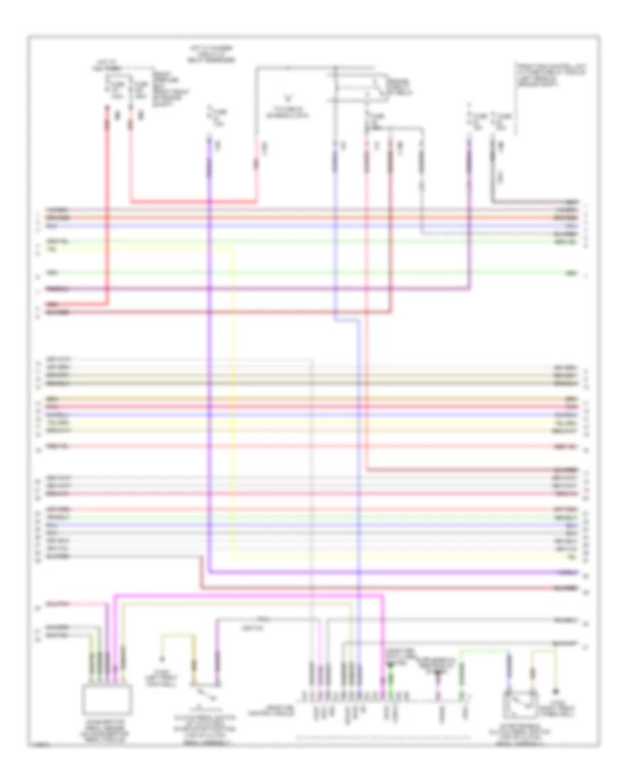
1.8L Turbo, Engine Performance Wiring Diagram (3 of 6) for Mercedes-Benz SLK250 2014
List of elements for 1.8L Turbo, Engine Performance Wiring Diagram (3 of 6) for Mercedes-Benz SLK250 2014:
- A-slp
- Accelerator pedal sensor (on accelerator pedal module)
- As-aav
- C14m
- C16s
- C3m
- C4i
- C6i
- C9g
- Can-e-l
- Clutch pedal switch (m/t & w/o eco start/stop function) (top of clutch
- Computer data lines system
- Crash
- Engine circuit 87 relay
- Front prefuse box (right front of engine compt)
- Front sam control unit w/ fuse & relay module (left rear of engine compt)
- Fuse 100a
- Fuse 150a
- Fuse 15a
- Fuse 20a
- Fuse 7.5a
- Hot at all times
- Hot w/ chassis circuit 87 relay energized
- Kup1
- Kup2
- Me-sfi (me) control module
- Mr1
- Mr2
- Pedal assembly)
- Pnk
- Red
- Reg
- Sp1s
- Sp2s
- Start enable clutch pedal switch (top of clutch pedal assembly)
- To fuse 32 (diagram 2 of 6)
- W15/5 (left front footwell)
- W16/4 (right front wheelwell)
- X25/7-c2
- X26-1
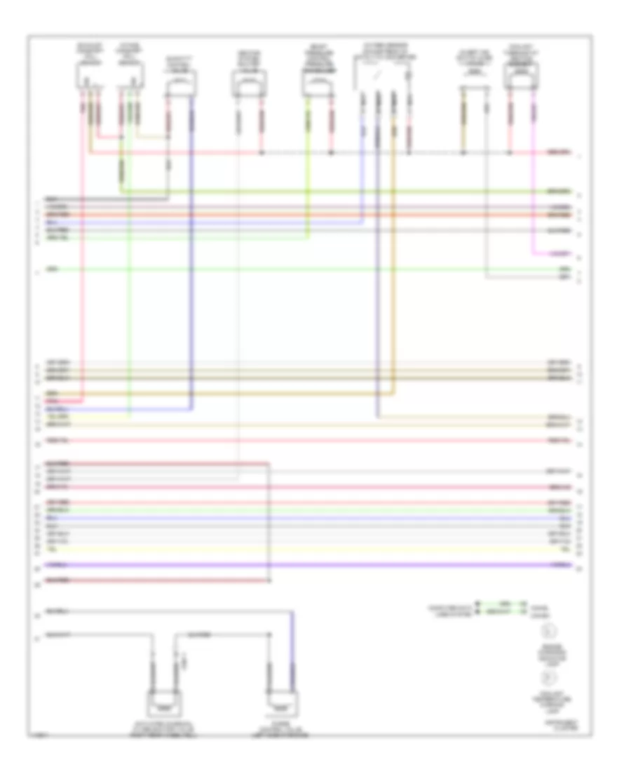
1.8L Turbo, Engine Performance Wiring Diagram (4 of 6) for Mercedes-Benz SLK250 2014
List of elements for 1.8L Turbo, Engine Performance Wiring Diagram (4 of 6) for Mercedes-Benz SLK250 2014:
- Activated charcoal filter shutoff valve (right rear wheelwell)
- Boost pressure control pressure transducer
- Can-eh
- Can-el
- Computer data lines system
- Coolant temperature warning lamp
- Coolant thermostat heating element
- Divert air switch over valve
- Engine diagnosis indicator lamp
- Exhaust camshaft hall sensor
- Heating system shutoff valve
- Instrument cluster
- Intake camshaft hall sensor
- Nca
- Oxygen sensor downstream of catalytic converter
- Pnk
- Purge control valve (left side of engine)
- Quantity control valve
- Sig
- X25/7-1
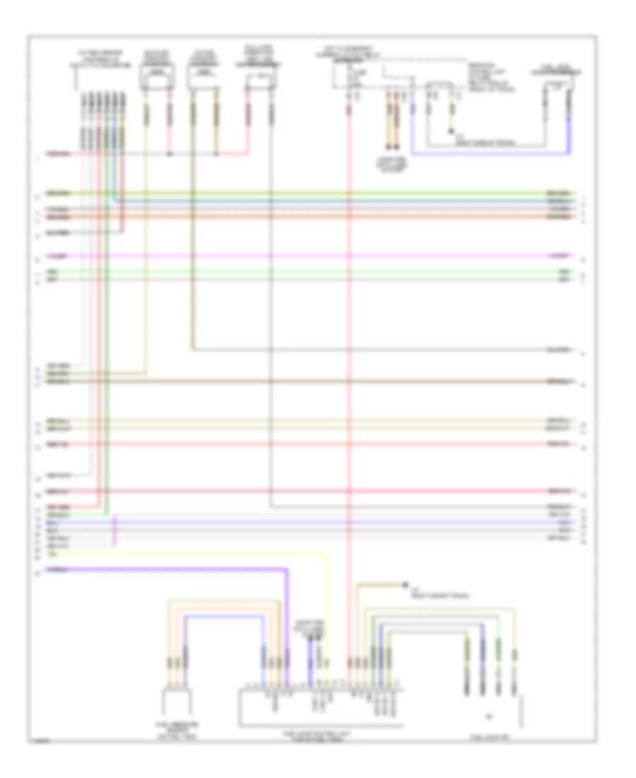
1.8L Turbo, Engine Performance Wiring Diagram (5 of 6) for Mercedes-Benz SLK250 2014
List of elements for 1.8L Turbo, Engine Performance Wiring Diagram (5 of 6) for Mercedes-Benz SLK250 2014:
- (+)
- (-)
- C3i
- C5h
- C7i
- C9i
- Can c h
- Can c l
- Computer data lines system
- Ekp
- Ekp-ec-u
- Ekp-ec-v
- Ekp-ec-w
- Exhaust camshaft solenoid
- Fuel level indicator sensor
- Fuel pressure sensor (on fuel tank)
- Fuel pump (fp)
- Fuel pump control unit (top of fuel tank)
- Full-load operation vent line heater element
- Fuse 25a
- Gnd
- Hot w/ quiescent current cutout relay energized
- Intake camshaft solenoid
- Kds-sig
- Nca
- Oxygen sensor
- Rear sam control unit w/ fuse/ relay module (front of trunk)
- Red
- Upstream of catalytic converter
- W7 (right side of trunk)
1.8L Turbo, Engine Performance Wiring Diagram (6 of 6) for Mercedes-Benz SLK250 2014
List of elements for 1.8L Turbo, Engine Performance Wiring Diagram (6 of 6) for Mercedes-Benz SLK250 2014:
- (+)
- (+) 5v
- (-)
- +5 v
- Actuator motor
- At-kwhs
- At-kwtv
- Charge air temperature sensor
- Coolant temperature sensor
- Crankshaft hall sensor
- Cylinder 1 & 2 knock sensor
- Hall sensor
- Intake manifold swirl flap actuator motor
- Ip1s
- Ip2s
- Ipm
- Ks2-sig
- Lsu1vm
- Me-sfi (me) control module
- Mr uds
- Nca
- Nwve2
- Oil level check switch (lower left side of engine)
- Oss
- Potenti- ometer 1
- Potenti- ometer 2
- Pressure sensor downstream throttle valve
- Pressure sensor upstream of compressor impeller
- Pressure sensor upstream throttle valve
- Rail pressure sensor
- Sig
- Ta tans
- Throttle valve actuator
- Ths
- Tmot