STARTING/CHARGING
Charging Wiring Diagram for Mercedes-Benz SLK250 2014

List of elements for Charging Wiring Diagram for Mercedes-Benz SLK250 2014:
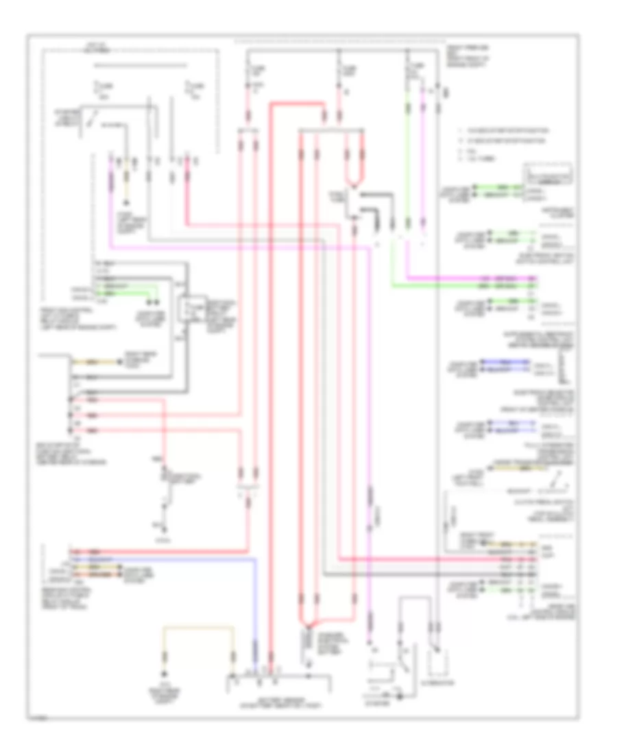
Starting Wiring Diagram for Mercedes-Benz SLK250 2014
List of elements for Starting Wiring Diagram for Mercedes-Benz SLK250 2014: