SHIFT INTERLOCK
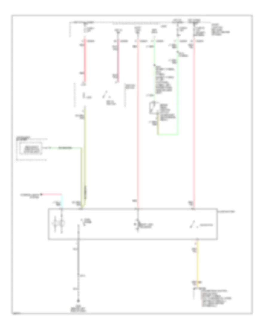
Shift Interlock Wiring Diagram for Ford Escape 2006
List of elements for Shift Interlock Wiring Diagram for Ford Escape 2006:
- (except hybrid: at left kick panel)
- (hybrid: left rocker panel, near driver's seat)
- Bpp input
- Brake pedal position switch (on bracket, above brake pedal)
- C175b
- C2280a
- C2280c
- C2280e
- Floor shifter
- Fuse 32 10a (except hybrid)
- Fuse 4 10a
- Fuse 6 15a
- G206 (behind left side of dash)
- Hot at all times
- Hot in run or start
- Ignition switch
- Instrument cluster
- Interior lights system
- Key in ign
- Key in ignition
- Lock
- Logic
- O/d switch
- Park range
- Powertrain control module (pcm) (except hybrid) (3.0l: in recess on upper center of firewall) (2.3l: rear center of firewall)
- Red
- Redundant park switch status input
- S214
- S310 (hybrid)
- S314 (hybrid)
- S331 (except hybrid)
- Shift lock sol
- Shift lock solenoid
- Smart junction box (sjb) (below center of dash)
 Čeština
 Deutsch
 Ελληνικά
 English
 English
 Español
 Suomi
Suomi Français
 Français
 עברית
עברית Hrvatski
 Magyar
 Italiano
 日本語
日本語 한국어
한국어 Nederlands
 Polski
 Português
 Português
 Română
 Русский
 Slovenčina
 Slovenščina
 Svenska
 Türkçe
 中文 (中国)
 Dansk
Dansk