AIR CONDITIONING
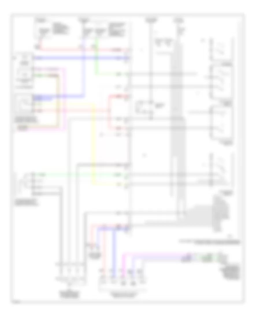
Automatic A/C Wiring Diagram (1 of 2) for Infiniti FX35 2003

List of elements for Automatic A/C Wiring Diagram (1 of 2) for Infiniti FX35 2003:
- (power) gnd
- 12a
- A/c and av switch
- Acc
- Aircon sw
- Amb sens
- Ambient sensor (below lower left side of front grille)
- Bat
- Blower motor (behind lower right side of dash)
- Blower relay
- Blwr fan sw
- Body control module (behind left kick panel)
- Bus+
- Bus-
- Can-h
- Can-l
- Comp ecv
- Comp on
- Computer data lines system
- Dcu- dsp
- Display
- Display control unit
- Display unit
- Driver side air mix door motor (behind lower left center of dash)
- Dsp gnd
- Dsp shield
- Dsp- dcu
- Dsp-dcu
- Dsu-dsp
- Fan on
- Fan pwm out
- Fuse 10a
- Fuse 15a
- Fuse block (j/b) (behind left kick panel)
- Gnd
- Hot at all times
- Hot in acc and on
- Hot in acc or start
- Hot in run or start
- Ign
- Ign2
- In-vehicle sensor (behind left center of dash)
- Incar sens
- Intake door motor (behind right side of dash)
- Intake sens
- Intake sensor (behind right side of dash, on evaporator assembly)
- Lan sig
- M45 (behind left side of dash, right of steering column)
- M56
- M57
- M64
- M85 (behind right side of dash, above blower motor)
- Mode door motor (behind left center of dash)
- Nca
- Passenger side air mix door motor (behind lower right center of dash)
- Pnk
- Red
- Sens gnd
- Shield
- Sun sens
- Sunload sensor (upper right side of dash, near base of windshield)
- Unified meter and a/c amplifier (behind center of dash)
- Vactr
- W/ navigation
- W/o navigation
Automatic A/C Wiring Diagram (2 of 2) for Infiniti FX35 2003
List of elements for Automatic A/C Wiring Diagram (2 of 2) for Infiniti FX35 2003:
- +batt
- +ign
- A/c compressor
- A/c relay
- Air comp
- Avcc gnd
- Can-h
- Can-l
- Computer data lines system
- Cooling fan motor 1 (at right front of engine compartment)
- Cooling fan motor 2 (at left front of engine compartment)
- Cooling fan relay-1
- Cooling fan relay-2
- Cooling fan relay-3
- Cpu
- E21 (behind headlamp, on front right of inner fender)
- Ecv solenoid valve
- Engine control module (behind glove box)
- Fuse & fusible link & relay box (at right rear of engine compartment)
- Fuse 10a
- Fuse 15a
- Fusible link e 80a
- Fusible link g 40a
- Fusible link h 40a
- Fusible link holder (at right rear of engine compartment)
- Gnd-a
- Hot at all times
- Hot in run or start
- Ignition relay
- Intelligent power distribution module (engine room) (at right front of engine compartment)
- Magnet clutch
- Motor fan-1
- Motor fan-2
- Motor fan-3
- Pd- pres
- Red
- Refrigerant pressure sensor (right front of engine compt, near radiator filler neck)