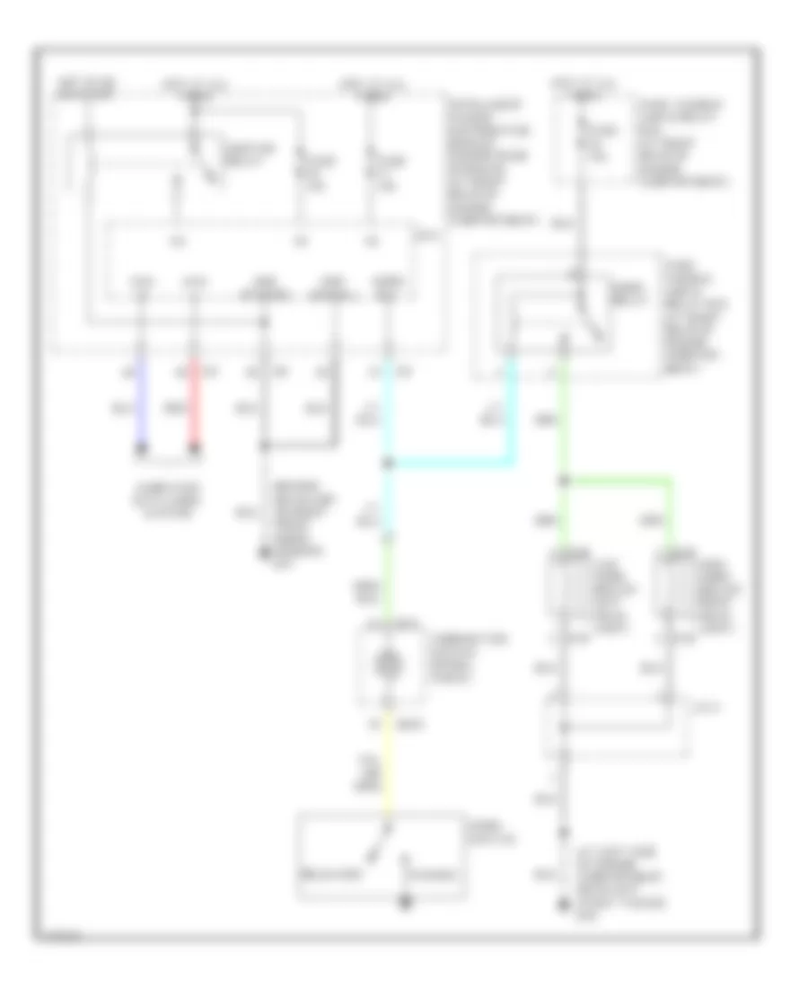
HORN
Horn Wiring Diagram for Infiniti FX35 2003
List of elements for Horn Wiring Diagram for Infiniti FX35 2003:
- (at left side of engine compartment, near left strut tower) e50
- (behind headlamp, on right front inner fender) e21
- +ig
- Can -h
- Can -l
- Combination switch (spiral cable)
- Computer data lines system
- Cpu
- E35
- E36
- E37
- E38
- Fuse 10a
- Fuse 15a
- Fuse, fusible link & relay box (at right rear of engine compart- ment)
- Fuse, fusible link & relay box (at right rear of engine compartment)
- Gnd (power)
- Gnd (signal)
- High horn (below right head- light)
- Horn relay
- Horn rly
- Horn switch
- Hot at all times
- Hot in on or start
- Ignition relay
- Intelligent power distribution module engine room (ipdm e/r) (at right rear of engine compartment)
- J/c 2
- Low horn (below left head- light)
- M15
- M203
- Pushed
- Red
- Released
 English