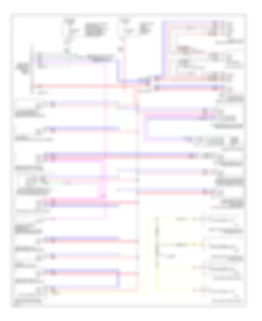
COMPUTER DATA LINES
Computer Data Lines Wiring Diagram for Infiniti FX35 2003
List of elements for Computer Data Lines Wiring Diagram for Infiniti FX35 2003:
- (4 doors)
- (behind left side of dash, right of steering column)
- A/c & av switch
- Abs actuator & electric unit (at left rear of eng compt)
- Air bag diagnosis sensor unit (under center console, behind gear selector)
- Awd control unit (behind right kick panel)
- Body control module (behind left kick panel)
- Bus +
- Bus -
- Bus shield
- Can-h
- Can-l
- Combination meter
- Cpu
- Data link connector (lower left side of dash)
- Diag-k
- Display control unit (w/navigation) (behind center of dash)
- Display unit (behind center of dash)
- Driver seat control unit (under driver seat)
- Engine control module (behind right kick panel)
- Front power window switch (passenger side)
- Fuse 19 10a
- Fuse 89 10a
- Fuse block (j/b) (behind left kick panel)
- Hot at all times
- Hot in on or start
- Icc sensor (behind center of front bumper)
- Icc unit (behind glove box)
- Intelligent key unit (behind left end of dash)
- Intelligent power distribution module engine room (at eight rear corner of engine compartment)
- Intelligent power distribution module engine room (at right rear of eng compt)
- K-line
- Left rear power window
- Low tire pressure warning control unit (behind right side of dash)
- M20
- M45
- M76
- Nca
- Power window main switch (driver side)
- Pwr wdo serial link
- Red
- Right rear power window
- Rx (comb meter)
- Shield
- Steering angle sensor (below left side of dash, near steering column)
- Transmission control module
- Tx (comb meter)
- Unified meter & a/c amplifier (behind center of dash)
- Unified meter control unit
- Vdc/tcs/abs control unit
- W/ navigation
- W/o navigation
 English