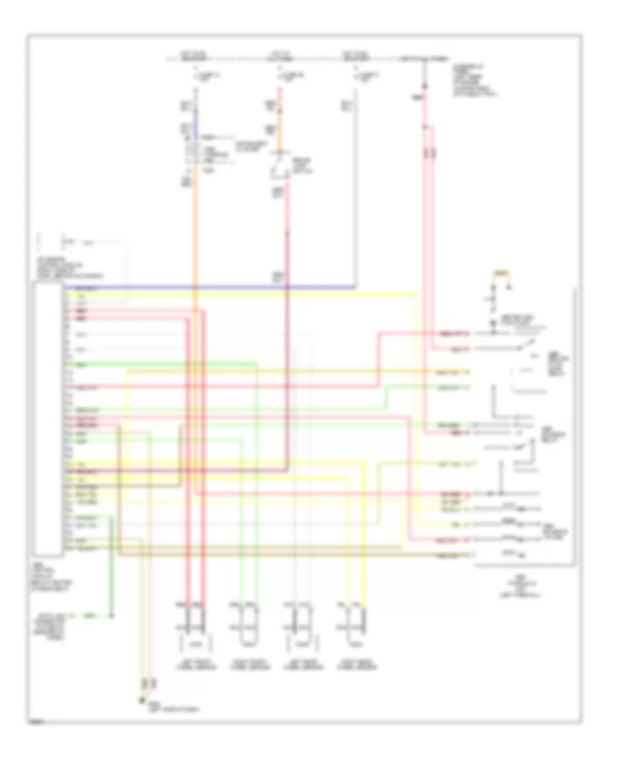
AUTOMOTIVE ELECTRICIANS PORTAL

ANTI-LOCK BRAKES – Audi Cabriolet 1997 – SYSTEM WIRING DIAGRAMS

ANTI-LOCK BRAKES

Anti-lock Brakes Wiring Diagram for Audi Cabriolet 1997

Anti-lock Brakes Wiring Diagram for Audi Cabriolet 1997 https://portal-diagnostov.com/license.html
https://portal-diagnostov.com/license.html Automotive Electricians Portal FZCO Automotive Electricians Portal FZCO
Get access to all wiring diagrams of the carDownload PDF file

List of elements for Anti-lock Brakes Wiring Diagram for Audi Cabriolet 1997:

  • (below center
  • (left firewall)
  • Abs
  • Abs control
  • Abs return flow pump
  • Abs return flow pump relay
  • Abs solenoid relay
  • Abs solenoid valves
  • Abs warning ind
  • All times
  • Brake lamp switch
  • Data link connector (in plenum, near relay panel)
  • Fuse 12 15a
  • Fuse 29 10a
  • Fuse 31 15a
  • Fuse/relay panel (left rear of engine compartment on plenum tray)
  • G202 (left side of dash)
  • Hot at
  • Hot at all times
  • Hot in on or start
  • Hydraulic
  • Instrument cluster
  • Left front wheel sensor
  • Left rear wheel sensor
  • Mfi engine control module (right side of dash, behind glove box)
  • Module
  • Nca
  • Of rear seat)
  • Red
  • Red red
  • Right front wheel sensor
  • Right rear wheel sensor
  • T26a
  • Unit