WARNING SYSTEMS
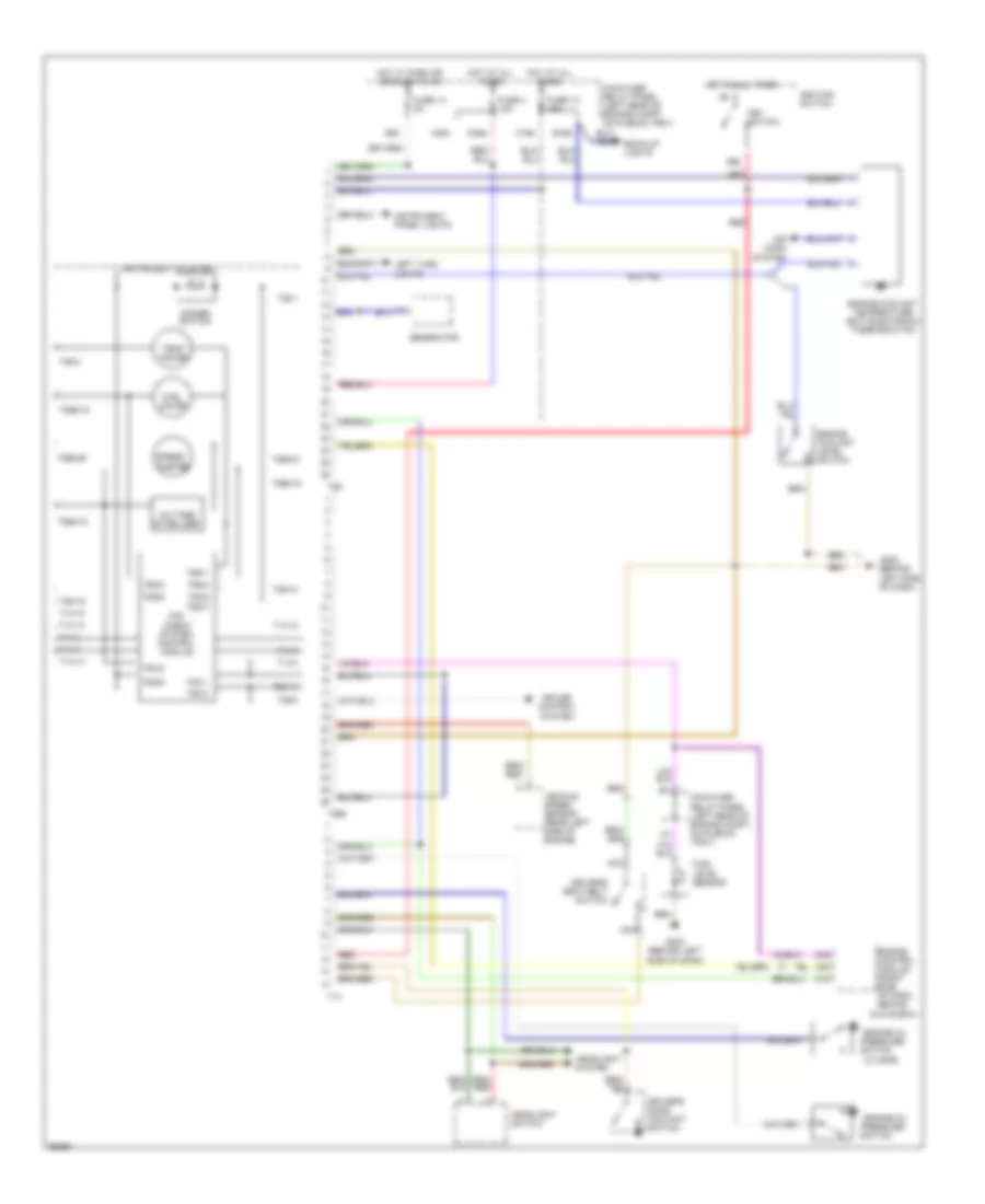
Warning Systems Wiring Diagram for Audi Cabriolet 1997
List of elements for Warning Systems Wiring Diagram for Audi Cabriolet 1997:
- (0.3 bar)
- (behind left side of dash)
- 86s
- Air cond system
- B15a
- C10
- C15a
- C23
- C24
- Cruise control system
- Dimmer switch
- Driver's door contact switch
- Driver's seat belt switch
- Engine control module (right side of dash, behind
- Engine coolant level switch
- Engine coolant temperature (ect) electronic thermoswitch
- Engine oil pressure
- F30al
- Fuel gauge
- Fuel level sensor
- Fuse 12 15a
- Fuse 14 5a
- Fuse 4 15a
- G202
- G202 (behind left side of dash)
- Generator
- Glove box)
- H30b
- Headlight switch
- Headlight system
- Hot at all times
- Hot w/ park or headlights on
- I58d
- Ignition switch
- Instrument cluster
- Instrument panel lights
- Key switch
- Left turn lights
- Main fuse/ relay panel (left rear of engine compt, on plenum tray)
- Mini check system control module
- Nca
- Red
- Speed- ometer
- Switch
- T14
- T14-10
- T14-12
- T14-13
- T14-14
- T14-3
- T14-4
- T14-7
- T14-9
- T26
- T26-1
- T26-10
- T26-13
- T26-19
- T26-2
- T26-8
- T26a
- T26a-15
- T26a-16
- T26a-18
- T26a-20
- T26a-21
- T5c/1
- T5c/2
- T5c/3
- T5c/5
- T6g/1
- T6g/2
- T6g/3
- T6g/4
- T6g/5
- T6g/6
- Temp gauge
- Vehicle speed sensor (rear left side of engine)
- Voltage stabilizer
 English