TRANSMISSION
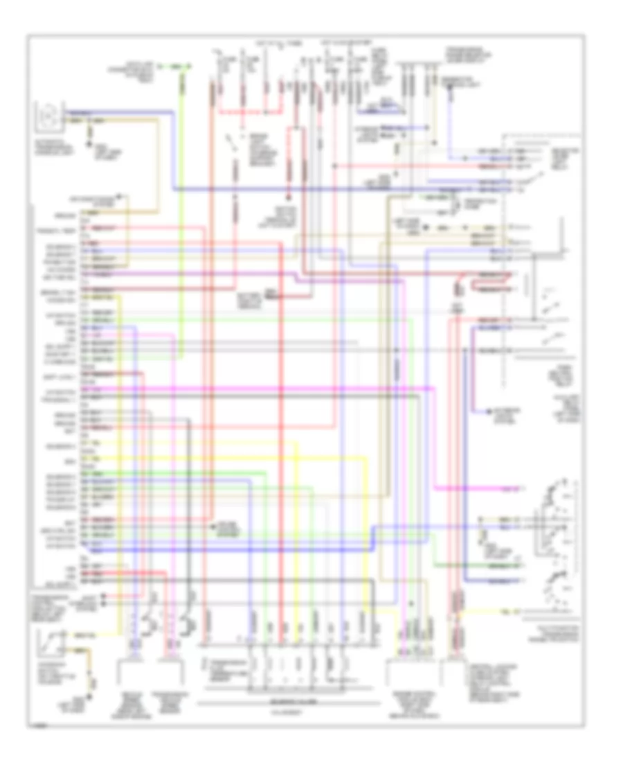
A/T Wiring Diagram for Audi Cabriolet 1997
List of elements for A/T Wiring Diagram for Audi Cabriolet 1997:
- (left side of dash)
- (left side of dash) g202
- 2-5
- 25-28
- 30-39
- 48-53
- 52-53
- 7-8
- 87a
- A/c kickdn
- Air conditioning system
- Automatic transmission console light
- Auxiliary relay panel (left side of dash)
- B11
- Bat
- Brake light switch (on brake support bracket)
- Brake lt sw
- C10
- C15a
- Central locking/ alarm system/ interior light delay control module (behind right side of rear seat)
- Cruise control system
- Data link connector (dlc) (in plenum tray)
- E50a
- Ecm
- Engine control module (ecm) (right side of dash, behind glove box)
- Exterior lights system
- F30al
- F50z
- Fuse 10a
- Fuse 15a
- Fuse 5a
- Fuse/ relay panel (left side plenum tray)
- G202 (left side of dash)
- Generator warning light
- Ground
- Hot at all times
- Hot in on or start
- Ign time adj
- Ignition switch terminal 50 (hot in start)
- Interior lights system
- K wire diag
- Kickdn sw
- Kickdown switch (on throttle housing)
- L30
- M-f switch
- Multi-function transmission range (tr) switch
- Nca
- On/start v
- Park/ neutral position relay
- Pk/neut sig
- Protection diode
- R n
- Red
- Red/ battery positive terminal
- Rpm sig
- Selector lever light relay
- Shft lk rly
- Shift interlock system
- Sol supp v
- Solenoid 1
- Solenoid 2
- Solenoid 3
- Solenoid 4
- Solenoid 5
- Solenoid 6
- Solenoid 7
- Solenoid valves
- Spd ctrl sw
- Tps signal v
- Tr display
- Trans fl temp
- Transmission control module (tcm) (below left rear seat)
- Transmission fluid temperature sensor
- Transmission range selector lever display
- Transmission vehicle speed sensor
- Valve body
- Vehicle speed sensor (rear left side of engine)
- Vss
 English