ANTI-LOCK BRAKES
Anti-lock Brakes Wiring Diagram for Honda Fit 2009
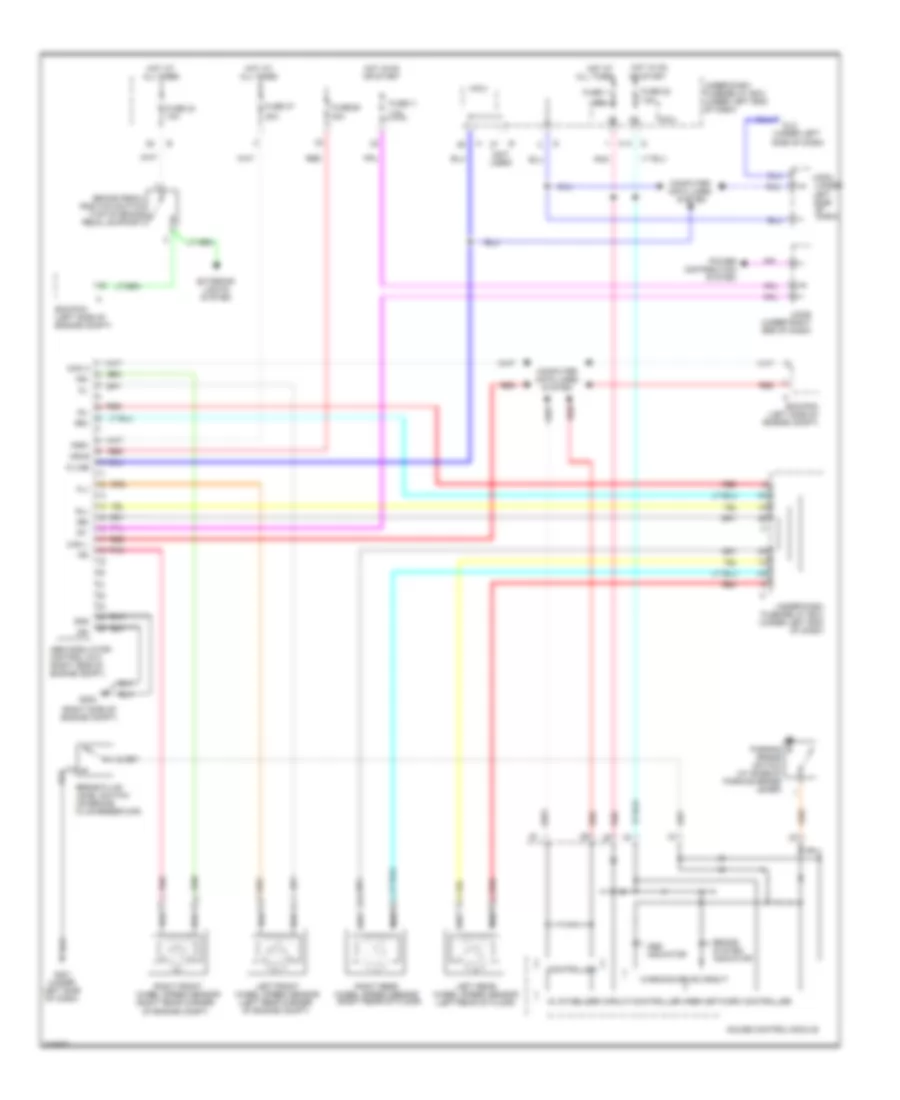
List of elements for Anti-lock Brakes Wiring Diagram for Honda Fit 2009:
- (not used)
- (right rear corner of engine compt)
- (right side of engine compt)
- (under
- (under left
- 10a
- 30a
- 7.5a
- Abs indicator
- Abs modulator- control unit (right side of engine compt)
- All times
- Brake fluid level switch (on brake fluid reservoir)
- Brake pedal position switch (top of brake pedal support)
- Brake system indicator
- Can h
- Can l
- Computer data lines system
- Computer data lines system
- Dash)
- Dlc
- Ecm/pcm (left side of engine compt)
- Exterior lights system
- Fl+
- Fl-
- Fr+
- Fr-
- Fsr+
- Fuse 1
- Fuse 11
- Fuse 22
- Fuse 24 10a
- Fuse 37
- Fuse 58
- G202
- G401 (under left side of dash)
- Gauge control module
- Gnd
- Hot at
- Hot at all times
- Hot in on or start
- Ig1
- Jc205 (under right end of dash)
- Jc504
- K-line
- Left side
- Left front wheel speed sensor (left rear corner of engine compt)
- Left rear wheel speed sensor (left rear of floor)
- Micu
- Mr+b
- Mr-
- Of
- Parking brake switch (at base of parking brake lever)
- Pnk
- Power distribution system
- Red
- Right front wheel speed sensor
- Right rear wheel speed sensor (right rear of floor)
- Rl+
- Rl-
- Rr+
- Rr-
- Side of dash)
- Under-dash fuse/relay box (under left end of dash)
- Warning drive circuit
 English