ENGINE PERFORMANCE
1.5L
1.5L, Engine Performance Wiring Diagram (1 of 5) for Honda Fit 2009

List of elements for 1.5L, Engine Performance Wiring Diagram (1 of 5) for Honda Fit 2009:
- A/f sensor relay
- A10
- A11
- A12
- A13
- A14
- A15
- A16
- A17
- A18
- A19
- A20
- A21
- A22
- A23
- A24
- A25
- A26
- A27
- A28
- A29
- A30
- A31
- A32
- A33
- A34
- A35
- A36
- A37
- A38
- A39
- A40
- A41
- A42
- A43
- A44
- A45
- A46
- A47
- A48
- A49
- Acc
- Air conditioning system
- App sensor (under left side of dash)
- Apsa
- Apsb
- B14
- B15
- B17
- B22
- B25
- B28
- Barometer sensor
- Bksw
- Bkswnc
- Brake pedal position switch (top of brake pedal support)
- C14
- C15
- Cable reel (in steering wheel)
- Canh
- Canl
- Clutch pedal position switch (m/t) (top of clutch pedal support)
- Computer data lines system
- Cooling fans system
- Crmtcls
- Ecm/pcm (left side of engine compt)
- Ect sensor 2 (lower right front of engine compt)
- Ect2
- Eld
- Eps control unit (under left end of dash)
- Etcsrly
- Evap canister vent shut valve (under middle of vehicle)
- Evaporator temperature sensor (behind glove box)
- Fanc
- Ftp
- Ftp sensor (under middle of vehicle)
- Fuse 12 10a
- Fuse 24 10a
- Fuse 26 10a
- Fuse 7 10a
- G401 (under left side of dash)
- G501 (under left side of dash)
- Hot at all times
- Hot in run or start
- Imofpr
- J/c c205 (under right end of dash)
- Lights system exterior
- Micu
- Nep
- Paddle shifter (+) upshift switch (if equipped)
- Paddle shifter (-) downshift switch (if equipped)
- Pnk
- Power input
- Red
- Relay ctrl
- S-net
- S-net 5v
- Scs
- Sdnp
- Sg4
- Sg5
- Sg6
- Sls
- Sound systems
- Starting/charging system
- Steering wheel
- Subrly
- Supp
- Tac
- Under-dash fuse/relay box (under left end of dash)
- Vbsol
- Vcc4
- Vcc5
- Vcc6
- Vssout
- Vsv
- Wen
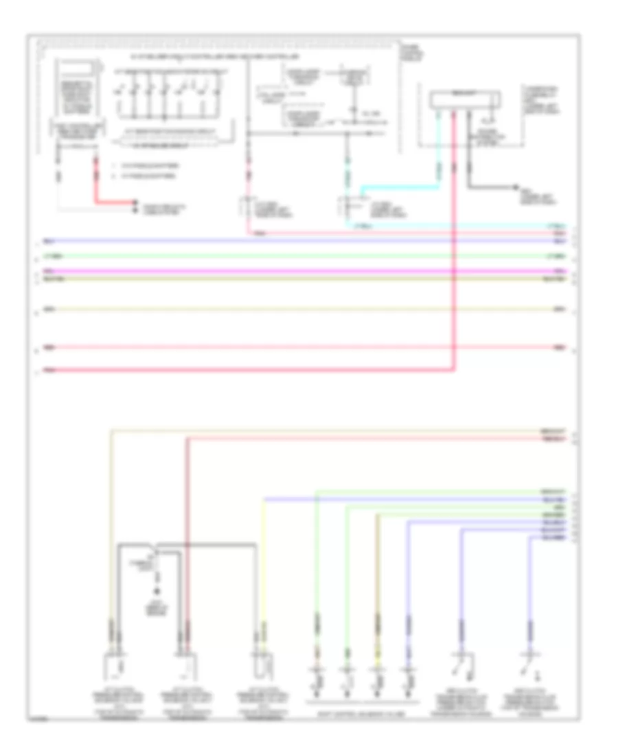
1.5L, Engine Performance Wiring Diagram (2 of 5) for Honda Fit 2009
List of elements for 1.5L, Engine Performance Wiring Diagram (2 of 5) for Honda Fit 2009:
- 10v stabilize circuit
- 2nd clutch transmission fluid pressure switch (top of transmission housing)
- 3rd clutch transmission fluid pressure switch (under automatic transmission housing)
- 5v stabilizer circuit/controller area network controller
- A/t clutch pressure control solenoid valve a (a/t) (top of automatic transmission)
- A/t clutch pressure control solenoid valve b (a/t) (top of automatic transmission)
- A/t clutch pressure control solenoid valve c (a/t) (top of automatic transmission)
- A/t gear position dimming circuit
- A/t gear position indicator drive circuit
- Compulsory turning-off circuit
- Compulsory turning-on circuit
- Computer data lines system
- Eld unit
- Fail safe circuit
- Fast controller area network transceiver
- G101 (rear of engine)
- G501 (under left side of dash)
- Gauge control module
- J/c c502 (under left side of dash)
- J/c c504 (under left side of dash)
- Mil ind
- Pnk
- Power distribution system
- Red
- S2 (thermal joint)
- Sequential sportshift mode shift indicator (w/ paddle shifters)
- Shift control solenoid valves
- Under-dash fuse/relay box (under left end of dash)
- W/ paddle shifters
- W/o paddle shifters
- Warning drive circuit
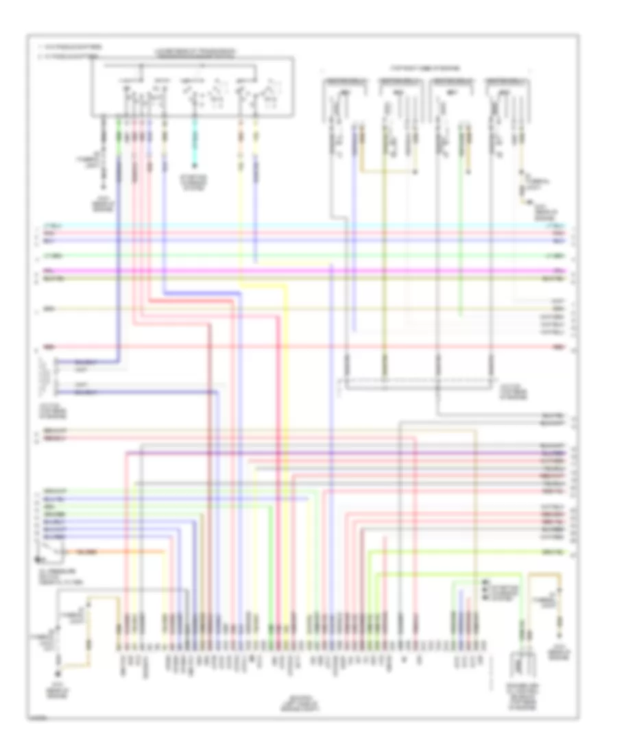
1.5L, Engine Performance Wiring Diagram (3 of 5) for Honda Fit 2009
List of elements for 1.5L, Engine Performance Wiring Diagram (3 of 5) for Honda Fit 2009:
- (lower rear of transmission) transmission range switch
- (top right side of engine)
- Altc
- Altf
- Altl
- Atft
- Atp2-1
- Atpd
- Atpd3
- Atpfwd
- Atpn
- Atpp
- Atpr
- Atprvs
- B10
- B11
- B12
- B13
- B14
- B15
- B16
- B17
- B18
- B19
- B20
- B21
- B22
- B23
- B24
- B25
- B26
- B27
- B28
- B29
- B30
- B31
- B32
- B33
- B34
- B35
- B36
- B37
- B38
- B39
- B40
- B41
- B42
- B43
- B44
- B45
- B46
- B47
- B48
- B49
- Ecm/pcm (left side of engine compt)
- Ect1
- Egr
- Egrp
- G101 (rear of engine)
- Gnd pg1
- Gnd pg2
- Iat
- Icm
- Ignition coil 1
- Ignition coil 2
- Ignition coil 3
- Ignition coil 4
- J/c c103 (top rear of engine)
- J/c c104 (top rear of engine)
- Lsa
- Lsb
- Lsc
- Oil pressure switch (near oil filter)
- Op2sw
- Op3sw
- Opsw
- Pcs
- Pnk
- Red
- Rocker arm oil control solenoid (top rear of engine)
- S1 (thermal joint)
- S2 (thermal joint)
- S2 (thermal joint) (a/t)
- Sg2
- Sha
- Shb
- Shc
- Shd
- Sho2s
- So2shtc
- Starting/ charging system
- Vcc2
- Vg+
- Vg-
- Vts
- W/ paddle shifters
- W/o paddle shifters
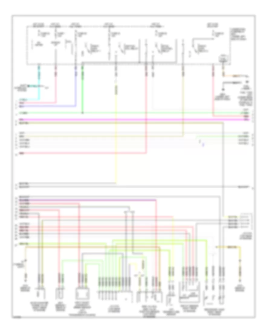
1.5L, Engine Performance Wiring Diagram (4 of 5) for Honda Fit 2009
List of elements for 1.5L, Engine Performance Wiring Diagram (4 of 5) for Honda Fit 2009:
- +b back up
- A/t
- Atf temperature sensor
- B14
- B18
- B24
- B31
- Ect sensor 1 (rear of engine)
- Egr valve & egr valve position sensor (top front of engine)
- Etcs control relay
- Evap canister purge valve (right rear of engine)
- Fuel pump
- Fuel tank unit (under rear of center console, in fuel tank)
- Fuse 1 10a
- Fuse 20 15a
- Fuse 22 7.5a
- Fuse 33 15a
- Fuse 39 15a
- Fuse 52 15a
- G101 (rear of engine)
- G502 (under left side of dash)
- Hot at all times
- Hot in on or start
- Iat sensor
- Ig1 meter
- Ignition coil relay
- Input shaft (mainshaft) speed sensor (a/t) (top of transmission housing)
- J/c c103 (top rear of engine)
- J/c c104 (top rear of engine)
- M/t
- Maf sensor
- Maf/iat sensor (right rear of engine)
- Micu
- Pgm-fi main relay 1
- Pgm-fi main relay 2
- Pnk
- Red
- S1 (thermal joint)
- Secondary ho2s (right rear of engine)
- Shift interlock system
- Under-dash fuse/relay box (under left end of dash)
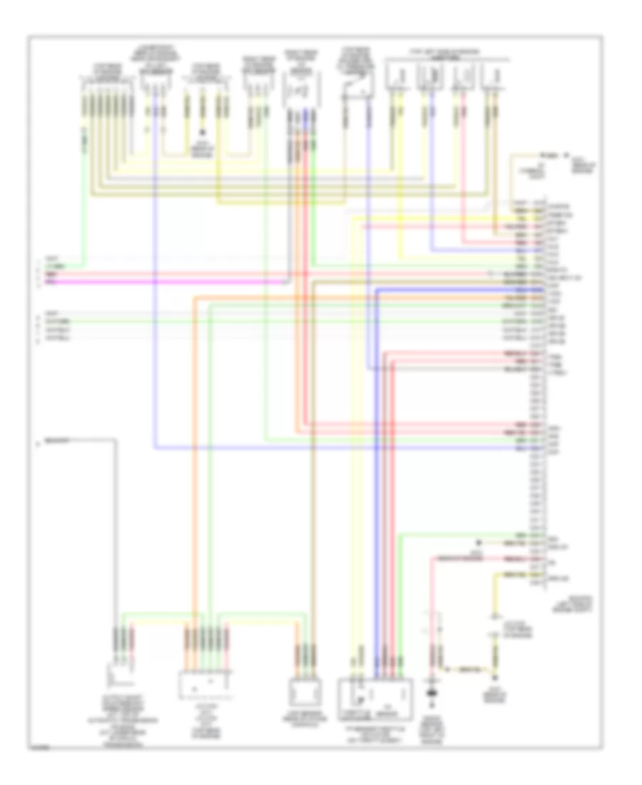
1.5L, Engine Performance Wiring Diagram (5 of 5) for Honda Fit 2009
List of elements for 1.5L, Engine Performance Wiring Diagram (5 of 5) for Honda Fit 2009:
- (lower right rear of engine, near crankshaft pulley) ckp sensor
- (right rear of engine) a/f sensor
- (right rear of engine) cmp sensor
- (top left side of engine) injectors
- (top rear of engine) j/c c103
- (top rear of engine) j/c c104
- (top rear of engine) rocker arm oil pressure switch
- Afs+
- Afs-
- Afshtc
- C10
- C11
- C12
- C13
- C14
- C15
- C16
- C17
- C18
- C19
- C20
- C21
- C22
- C23
- C24
- C25
- C26
- C27
- C28
- C29
- C30
- C31
- C32
- C33
- C34
- C35
- C36
- C37
- C38
- C39
- C40
- C41
- C42
- C43
- C44
- C45
- C46
- C47
- C48
- C49
- Ckp
- Cmp
- Ecm/pcm (left side of engine compt)
- Etcsm+
- Etcsm-
- G101 (rear of engine)
- Gnd lg1
- Gnd lg2
- Ig1etcs
- Ign input ig1
- Igpls1
- Igpls2
- Igpls3
- Igpls4
- Inj1
- Inj2
- Inj3
- Inj4
- J/c c103 (m/t) j/c c104 (a/t) (top rear of engine)
- J/c c103 (top rear of engine)
- Knock sensor (top left front of engine)
- Map
- Map sensor (rear of intake manifold)
- Output shaft countershaft speed sensor (a/t: top of automatic transmission housing) (m/t: under rear of manual transmission)
- Pgmetcs
- Red
- S1 (thermal joint)
- Sg1
- Sg3
- Throttle actuator
- Tp sensor
- Tp sensor/throttle actuator (on throttle body)
- Tpsa
- Tpsb
- Vcc1
- Vcc3
- Vtpsw