ELECTRONIC POWER STEERING
Electronic Power Steering Wiring Diagram for Honda Fit 2009
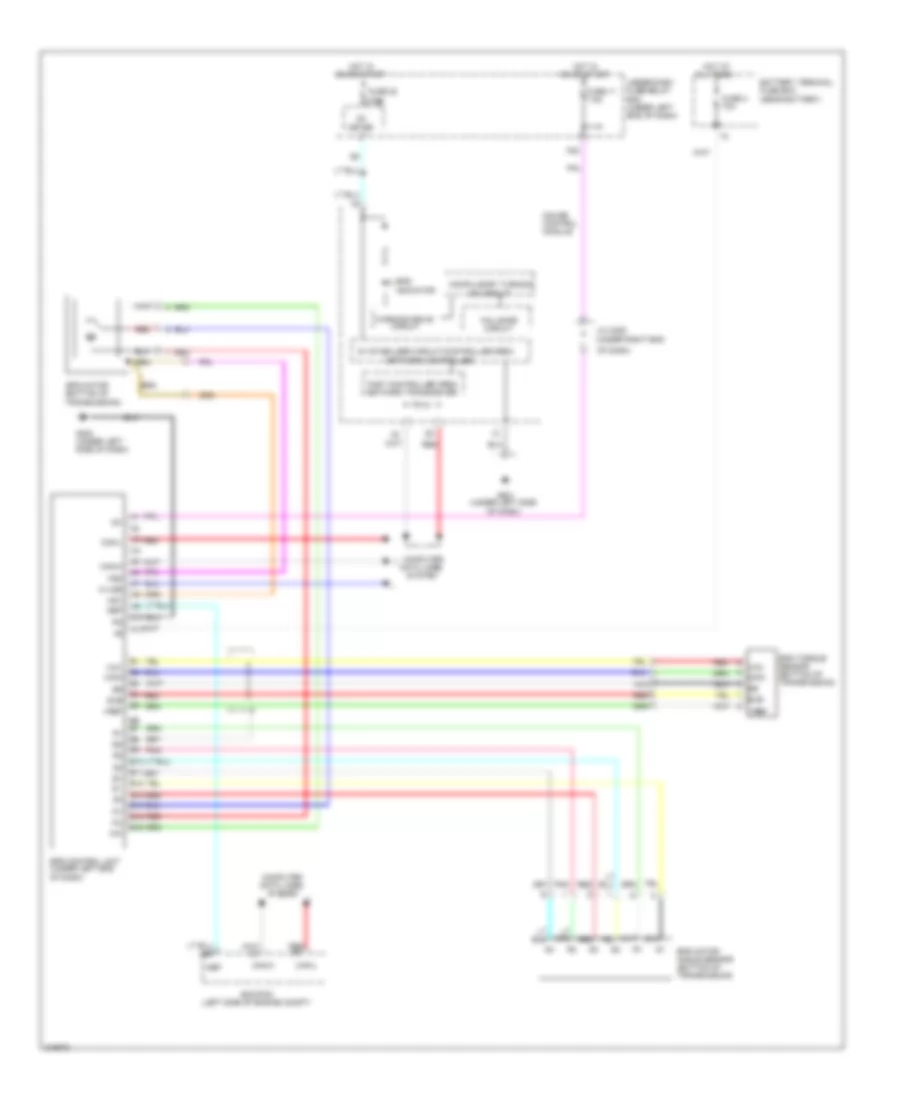
List of elements for Electronic Power Steering Wiring Diagram for Honda Fit 2009:
- (under right end
- 5v stabilizer circuit/controller area
- A10
- A11
- A32
- B10
- B11
- B12
- B13
- B14
- B15
- B16
- B6 b7
- Battery terminal fuse box (near battery)
- Can-h
- Can-l
- Compulsory turning
- Computer data lines system
- Ecm/pcm (left side of engine compt)
- Eps control unit (under left end of dash)
- Eps indicator
- Eps motor (bottom of transmission)
- Eps motor angle sensor (bottom of transmission)
- Eps torque sensor (bottom of transmission)
- Fail-safe circuit
- Fast controller area network transceiver
- Fuse 11 7.5a
- Fuse 2 70a
- Fuse 22 7.5a
- G203 (under left side of dash)
- G501 (under left side of dash)
- Gauge control module
- Hot at all times
- Hot in on or start
- Ig1
- J/c c205
- K-line
- Main
- Meter
- Mg1
- Mg2
- Nep
- Network controller
- Of dash)
- On circuit
- Pnk
- Red
- Sub
- Under-dash fuse/relay box (under left end of dash)
- Vcc
- Vref
- Warning drive circuit
 English