ANTI-LOCK BRAKES
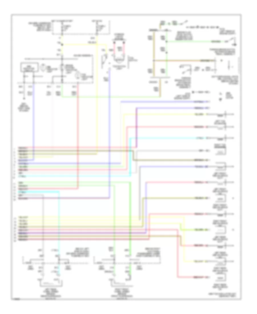
Anti-lock Brake Wiring Diagrams, with Traction Control (1 of 2) for Honda Odyssey EX 1999

List of elements for Anti-lock Brake Wiring Diagrams, with Traction Control (1 of 2) for Honda Odyssey EX 1999:
- (1999-00)
- (2001)
- (behind left kick panel) g200
- (below left side of dash) abs-tcs control unit
- (not used)
- A10
- A11
- A12
- A13
- A14
- A15
- A16
- A17
- A18
- A19
- A20
- A21
- A22
- A23
- A24
- A25
- A26
- A31
- Abs
- Abs fail- safe relay (near wind- shield washer reservoir)
- Abs pump motor relay (near wind- shield washer reservoir)
- Astftp
- Atsftp
- B10
- B11
- B12
- B13
- B14
- B15
- B16
- B4
- Brake pedal position switch (on brake pedal support)
- C10
- C11
- C12
- D11
- D16
- Data link connector (dlc) (on lower left of dash, above kick panel)
- Dlc
- Driver's underdash fuse/relay box (below left end of dash)
- E15
- Fl-in
- Fl-out
- Flw (+)
- Flw (-)
- Fp-tdr
- Fptdr
- Fr-in
- Fr-out
- Frw (+)
- Frw (-)
- Fsr
- Fuse 14 7.5a
- Fuse 3 10a
- Fuse 47 20a
- Fuse 48 20a
- Fuse 50 30a
- G101 (right front of engine compt)
- G115 (rear of engine)
- G200 (behind left
- Gauge assembly
- Gnd1
- Gnd2
- Gnd3
- H18
- Hot at all times
- Ig2
- K14
- Kick panel)
- Left front wheel speed sensor (front suspension knuckle)
- Lg2
- Mck
- Ncl
- Ncr
- Nep
- Nor
- Npe
- O20
- Park
- Passenger's underdash fuse/relay box (behind right kick panel)
- Pf-inh
- Pfinh
- Pmr
- Powertrain control module (behind lower center of dash)
- Right rear wheel speed sensor (rear suspension knuckle)
- Rl-in
- Rl-out
- Rlw (+)
- Rlw (-)
- Rr-in
- Rr-out
- Rrw (+)
- Rrw (-)
- Scs
- Stop
- Tachometer drive circuit
- Tcs relay (in multi-fuse relay box, left front of engine compt)
- Tcs sw
- Tcs1
- Tcs2
- Tcsr
- Test tachometer connector (on top of brake booster)
- Thlout
- Underhood fuse/relay box (right side of engine compt)
- Vref
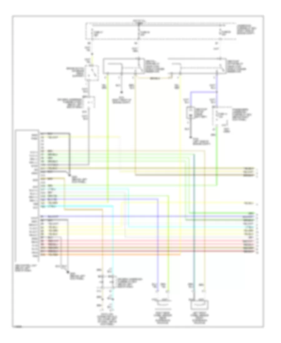
Anti-lock Brake Wiring Diagrams, with Traction Control (2 of 2) for Honda Odyssey EX 1999
List of elements for Anti-lock Brake Wiring Diagrams, with Traction Control (2 of 2) for Honda Odyssey EX 1999:
- (behind right kick panel) passenger's under- dash fuse/relay box
- (below left side of dash) driver's underdash fuse/relay box
- (not used)
- A17
- A18
- Abs indicator circuit
- Abs indicator light
- Abs pump motor
- Abs-tcs modulator unit (near battery)
- B11
- B13
- B14
- B16
- Brake fluid level switch (in brake fluid reservoir cap)
- Brake system indicator light
- C10
- C11
- C14
- C16
- Canada
- Daytime running lights (drl) control unit (behind center of dash)
- Driver's underdash fuse/relay box (below left end of dash)
- E16
- Fuse 4 7.5a
- Fuse 9 7.5a
- G100 (left side of engine compt)
- G116 (left rear of engine compt)
- G201 (behind right side of dash)
- Gauge assembly
- Hot in on
- Hot in on or start
- Interior lights system
- K10
- Left front abs solenoid (in)
- Left front abs solenoid (out)
- Left rear abs solenoid (in)
- Left rear abs solenoid (out)
- Left rear wheel speed sensor (rear suspension knuckle)
- Left tcs solenoids
- O10
- Parking brake switch (on parking brake pedal assembly)
- Red
- Right front abs solenoid (in)
- Right front abs solenoid (out)
- Right front wheel speed sensor (front suspension knuckle)
- Right rear abs solenoid (in)
- Right rear abs solenoid (out)
- Right tcs solenoids
- Tcs indicator light
- Tcs switch
- Tcs switch light
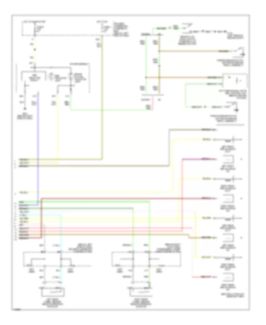
Anti-lock Brake Wiring Diagrams, without Traction Control (1 of 2) for Honda Odyssey EX 1999
List of elements for Anti-lock Brake Wiring Diagrams, without Traction Control (1 of 2) for Honda Odyssey EX 1999:
- (not used)
- A10
- A11
- A12
- A13
- A14
- A15
- A16
- A17
- A18
- A19
- A20
- A21
- A22
- Abs control unit (below left side of dash)
- Abs fail- safe relay (near wind- shield washer reservoir)
- Abs pump motor (near battery)
- Abs pump motor relay (near wind- shield washer reservoir)
- B10
- B11
- B12
- B4
- Brake switch (on brake pedal support)
- Data link connector (dlc) (on lower left of dash, above kick panel)
- Dlc
- Driver's underdash fuse/relay box (below left end of dash)
- E15
- Fl-in
- Fl-out
- Flw (+)
- Flw (-)
- Fr-in
- Fr-out
- Frw (+)
- Frw (-)
- Fsr
- Fuse 14 7.5a
- Fuse 47 20a
- Fuse 48 20a
- Fuse 50 30a
- G100 (left side of engine compt)
- G101 (right front of engine compt)
- G200 (behind left kick panel)
- Gnd1
- Gnd2
- Gnd3
- Gnd4
- H18
- Hot at all times
- Ig2
- K14
- Left front wheel sensor (front suspension knuckle)
- Mck
- O20
- Park
- Passenger's underdash fuse/relay box (behind right kick panel)
- Pmr
- Right rear wheel sensor (rear suspension knuckle)
- Rl-in
- Rl-out
- Rlw (+)
- Rlw (-)
- Rr-in
- Rr-out
- Rrw (+)
- Rrw (-)
- Scs
- Stop
- Underhood fuse/relay box (right side of engine compt)
- Walp
Anti-lock Brake Wiring Diagrams, without Traction Control (2 of 2) for Honda Odyssey EX 1999
List of elements for Anti-lock Brake Wiring Diagrams, without Traction Control (2 of 2) for Honda Odyssey EX 1999:
- (behind right kick panel) passenger's under- dash fuse/relay box
- (below left side of dash) driver's underdash fuse/relay box
- (not used)
- A17
- A18
- Abs indicator circuit
- Abs indicator light
- Abs modulator unit (near battery)
- B11
- B13
- B14
- B16
- Brake fluid level switch (in brake fluid reservoir cap)
- Brake system indicator light
- C10
- C11
- C14
- C16
- Canada
- Daytime running lights (drl) control unit (behind center of dash)
- Driver's underdash fuse/relay box (below left end of dash)
- E16
- Fuse 4 7.5a
- Fuse 9 7.5a
- G116 (left rear of engine compt)
- G201 (behind right side of dash)
- Gauge assembly
- Hot in on
- Hot in on or start
- K10
- Left front abs solenoid (in)
- Left front abs solenoid (out)
- Left rear abs solenoid (in)
- Left rear abs solenoid (out)
- Left rear wheel sensor (rear suspension knuckle)
- O10
- Parking brake switch (on parking brake pedal assembly)
- Right front abs solenoid (in)
- Right front abs solenoid (out)
- Right rear abs solenoid (in)
- Right rear abs solenoid (out)
- Right rear wheel sensor (rear suspension knuckle)