ANTI-THEFT
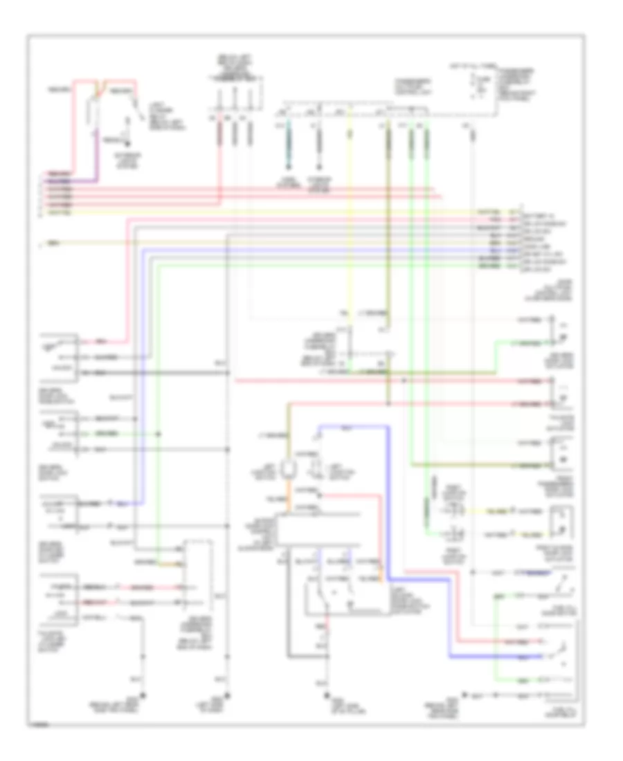
Anti-theft Wiring Diagram, EX (1 of 2) for Honda Odyssey EX 1999

List of elements for Anti-theft Wiring Diagram, EX (1 of 2) for Honda Odyssey EX 1999:
- 10a
- 15a
- 20a
- 7.5a
- A10
- A12
- A13
- A14
- A15
- A16
- A17
- A18
- A20
- A22
- A23
- A24
- B11
- B16
- B22
- Battery in
- Battery input
- Comm line
- Cylinder
- Disarm switch
- Door key
- Dr door sw
- Driver's door switch
- Driver's multiplex control unit
- Driver's underdash fuse/relay box (below left end of dash)
- Exterior lights system
- F pass dr sw
- Front
- Front pass door switch
- Front passenger's door lock switch
- Fuse 10
- Fuse 12
- Fuse 13
- Fuse 9
- G101 (right front of engine compt)
- G14
- G200 (behind left kick panel)
- G201 (behind right side of dash)
- G202 (below left side of dash)
- G202 (left side of dash)
- G305 (right side of "b" pillar)
- Ground
- Hood switch
- Horns
- Horns system
- Hot at all times
- Hot in on or start
- Ign input
- Ignition input
- Ignition key switch
- In-line fuse 1 (behind left side of dash)
- In-line fuse 2 (behind left side of dash)
- J12
- J14 red
- Key in ign input
- Keyless receiver unit (behind right end of dash)
- Left power sliding door control unit
- Left sliding door switch
- Lft slide dr sw
- Light flasher relay
- Lock
- Lt sliding door control
- O19
- Panic
- Pass key sw
- Pass lck sw
- Passenger's
- Passenger's multiplex control unit
- Passenger's underdash fuse/relay box (behind right kick panel)
- Pnk
- R slid dr sw
- Red
- Right power sliding door control unit
- Right side of dash) g201
- Right sliding door switch
- Rt sliding door control
- Security control unit (behind dash, right of steering column)
- Security diode
- Security diode (behind right kick panel)
- Security indicator
- Security led
- Shift interlock system
- Steering lock
- Switch
- Taillight relay
- Transmitter
- Unlock
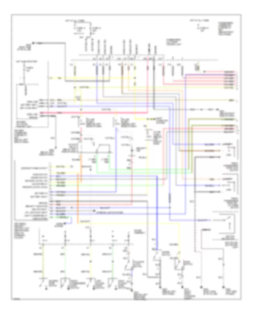
Anti-theft Wiring Diagram, EX (2 of 2) for Honda Odyssey EX 1999
List of elements for Anti-theft Wiring Diagram, EX (2 of 2) for Honda Odyssey EX 1999:
- (below left end of dash) driver's underdash fuse/relay box
- A11
- A12
- A15
- A16
- A17
- A18
- A21
- B11
- Battery in
- C14
- Comm line
- Door multiplex control unit (in driver's door)
- Dr key cyl sw
- Dr lck knob sw
- Dr lck sw
- Driver's door key cylinder switch
- Driver's door lock actuator
- Driver's door lock knob switch
- Driver's door lock switch
- Driver's underdash fuse/relay box (below left end of dash)
- Exterior lights system
- F17
- Front passenger's door lock actuator
- Fuel fill door relay
- Fuel fill door switch
- Fuse 20a
- G202 (left side of dash)
- G308 (left side of "b" pillar)
- G404 (behind left rear side trim panel)
- Ground
- Horn systems
- Hot at all times
- I18
- Interior lights system
- K13
- Left junction i
- Left junction switch
- Left sliding door lock knob switch/ actuator
- Light flasher relay (below left side of dash)
- Lock
- Lock key cylinder
- Passenger's multiplex control unit
- Passenger's underdash fuse/relay box (behind right kick panel)
- Pnk
- Red
- Right junction switch
- Right junction switch h
- Right sliding door lock actuator
- Sliding door lock control unit (in left sliding door)
- Switch
- Tailgate
- Tailgate lock actuator
- Unlock
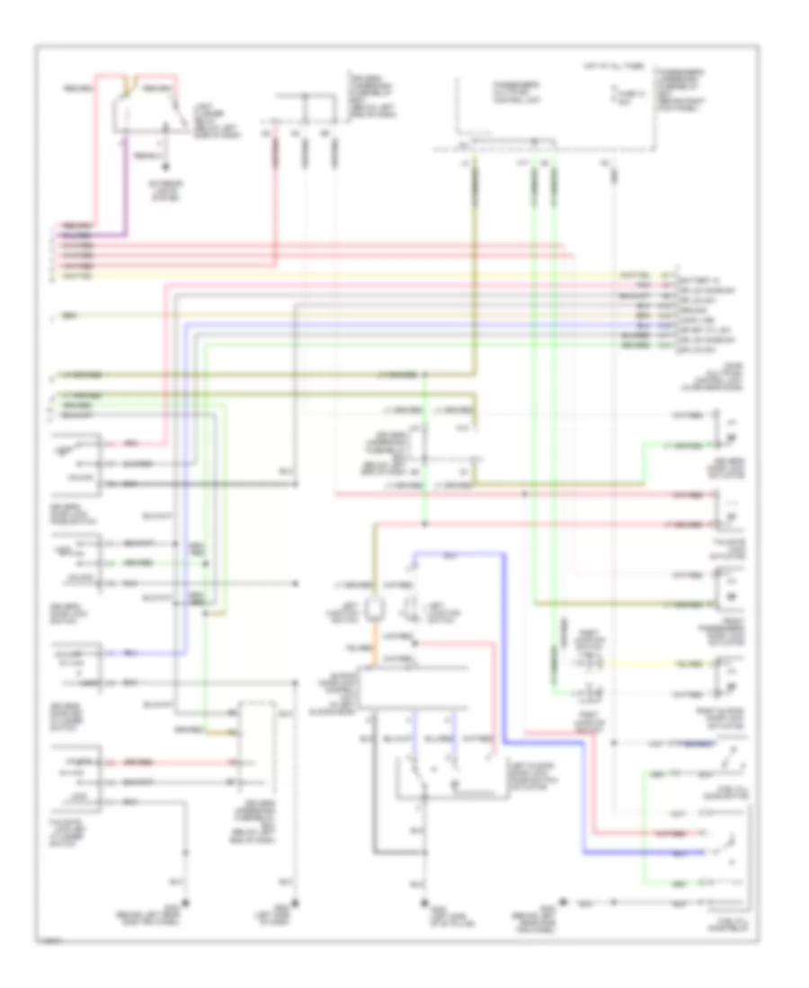
Anti-theft Wiring Diagram, LX (1 of 2) for Honda Odyssey EX 1999
List of elements for Anti-theft Wiring Diagram, LX (1 of 2) for Honda Odyssey EX 1999:
- 10a
- 15a
- 20a
- 7.5a
- A10
- A12
- A13
- A16
- A17
- A20
- A22
- A23
- A24
- B11
- B22
- Battery in
- Battery input
- Comm line
- Cylinder
- Disarm switch
- Door key
- Door switches output
- Dr door lck sw lck
- Dr door lck sw unlck
- Driver's door switch
- Driver's multiplex control unit
- Driver's underdash fuse/relay box (below left end of dash)
- F15
- Front
- Front passenger's door lock switch
- Front passenger's door switch
- Fuse 10
- Fuse 12
- Fuse 13
- Fuse 9
- G101 (right front of engine compt)
- G14
- G200 (behind left kick panel)
- G201 (behind right side of dash)
- G202 (below left side of dash)
- G202 (left side of dash)
- G305 (right side of "b" pillar)
- G404 (behind left rear side trim panel)
- Gauge assembly
- Ground
- Hood switch
- Horn system
- Horns system
- Hot at all times
- Hot in on or start
- Ign input
- Ignition input
- Ignition key switch
- Ignition key switch/key light
- In-line fuse 1 (behind left side of dash)
- In-line fuse 2 (behind left side of dash)
- In-line fuse 3 (behind left side of dash)
- Int lights sw input
- Interior lights system
- J12
- J14
- Key in ign input
- Keyless & security control unit (behind dash, right of steering column)
- Left sliding door switch
- Light flasher relay
- Lock
- O19
- Pass key sw
- Pass lck sw
- Passenger's
- Passenger's multiplex control unit
- Passenger's underdash fuse/relay box (behind right kick panel)
- Pnk
- Red
- Right sliding door switch
- Security indicator
- Security led
- Shift interlock system
- Switch
- Tailgate latch switch
- Unlock
- Unlock relay
- Unlock relay (below left side of dash)
Anti-theft Wiring Diagram, LX (2 of 2) for Honda Odyssey EX 1999
List of elements for Anti-theft Wiring Diagram, LX (2 of 2) for Honda Odyssey EX 1999:
- 20a
- A11
- A12
- A15
- A16
- A17
- A18
- Battery in
- Comm line
- Door multiplex control unit (in driver's door)
- Dr key cyl sw
- Dr lck knob sw
- Dr lck sw
- Driver's door key cylinder switch
- Driver's door lock actuator
- Driver's door lock knob switch
- Driver's door lock switch
- Driver's underdash fuse/relay box (below left end of dash)
- Exterior lights system
- F17
- Front passenger's door lock actuator
- Fuel fill door relay
- Fuel fill door switch
- Fuse 12
- G202 (left side of dash)
- G308 (left side of "b" pillar)
- G404 (behind left rear side trim panel)
- Ground
- Hot at all times
- I18
- K13
- Left junction i
- Left junction switch
- Left sliding door lock knob switch/ actuator
- Light flasher relay (below left side of dash)
- Lock
- Lock key cylinder
- Passenger's multiplex control unit
- Passenger's underdash fuse/relay box (behind right kick panel)
- Pnk
- Right junction switch
- Right junction switch h
- Right sliding door lock actuator
- Sliding door lock control unit (in left sliding door)
- Switch
- Tailgate
- Tailgate lock actuator
- Unlock
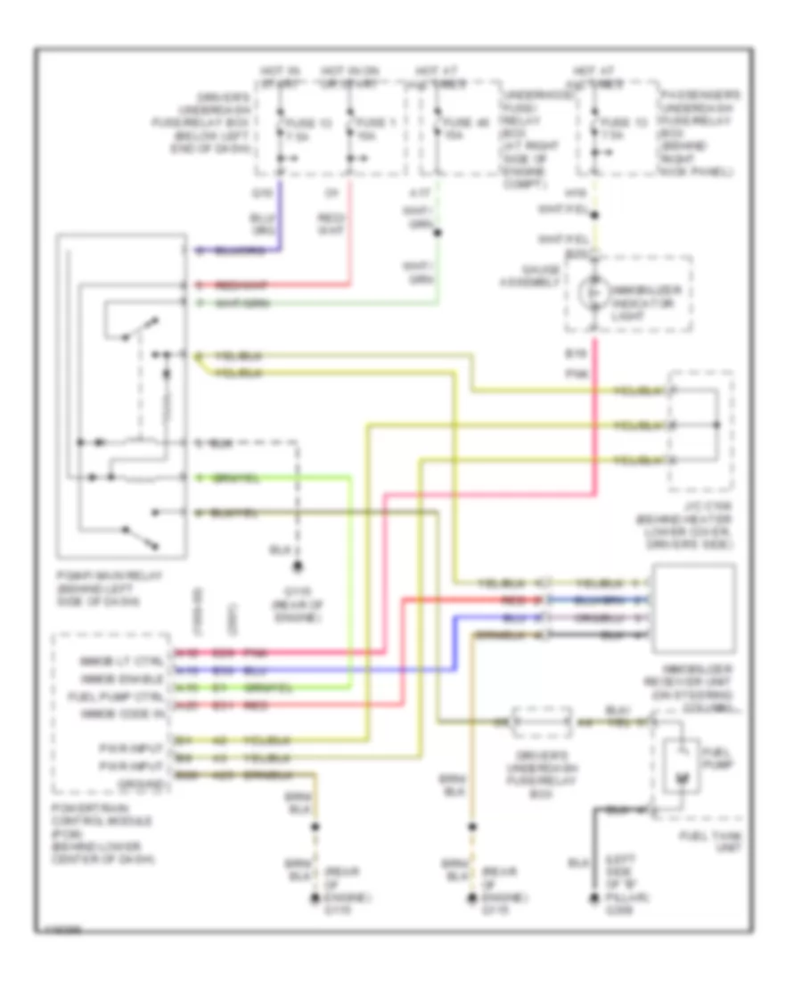
Immobilizer Wiring Diagram for Honda Odyssey EX 1999
List of elements for Immobilizer Wiring Diagram for Honda Odyssey EX 1999:
- (1999-00)
- (2001)
- (left side of "b" pillar) g308
- (rear of engine) g115
- A12
- A13
- A15
- A17
- A25
- B19
- B20
- Driver's underdash fuse/relay box
- Driver's underdash fuse/relay box (below left end of dash)
- E29
- E30
- E31
- Fuel pump
- Fuel pump ctrl
- Fuel tank unit
- Fuse 1 15a
- Fuse 13 7.5a
- Fuse 46 15a
- G115 (rear of engine)
- Gauge assembly
- Ground
- H16
- Hot at all times
- Hot in on or start
- Hot in start
- Immob code in
- Immob enable
- Immob lt ctrl
- Immobilizer indicator light
- Immobilizer receiver unit (on steering column)
- J/c c106 (behind heater lower cover, driver's side)
- Passenger's underdash fuse/relay box (behind right kick panel)
- Pgm-fi main relay (behind left side of dash)
- Pnk
- Powertrain control module (pcm) (behind lower center of dash)
- Pwr input
- Q10
- Red
- Underhood fuse/ relay box (at right side of engine compt)