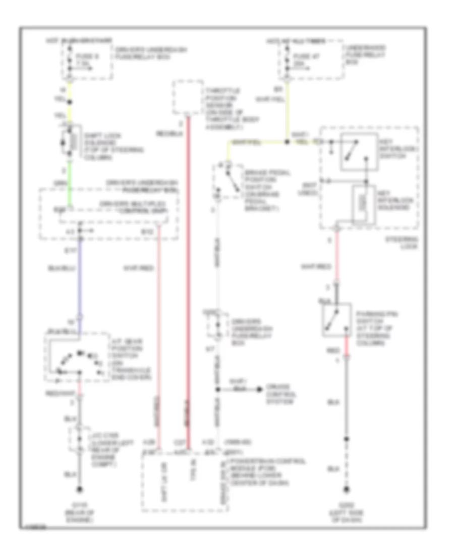
SHIFT INTERLOCKS
Shift Interlock Wiring Diagram for Honda Odyssey EX 1999
List of elements for Shift Interlock Wiring Diagram for Honda Odyssey EX 1999:
- (1999-00)
- (2001)
- (not used)
- A/t gear position switch (on transaxle end cover)
- A15
- A28
- A32
- B12
- B22
- Brake pedal position switch (on brake pedal bracket)
- Brake sw in
- C27
- Cruise control system
- Driver's multiplex control unit
- Driver's underdash fuse/relay box
- E15
- E17
- Fuse 47 20a
- Fuse 9 7.5a
- G115 (rear of engine)
- G202 (left side of dash)
- Hot at all times
- Hot in on or start
- J/c c105 (lower left rear of engine compt)
- Key interlock solenoid
- Key interlock switch
- O20
- Parking pin switch (at top of steering column)
- Powertrain control module (pcm) (behind lower center of dash)
- Red
- Shft lk cir
- Shift lock solenoid (top of steering column)
- Steering lock
- Throttle position sensor (on side of throttle body assembly)
- Tps in
- Underhood fuse/relay box
 English