ANTI-LOCK BRAKES
Anti-lock Brakes Wiring Diagram for Honda Odyssey Touring 2007
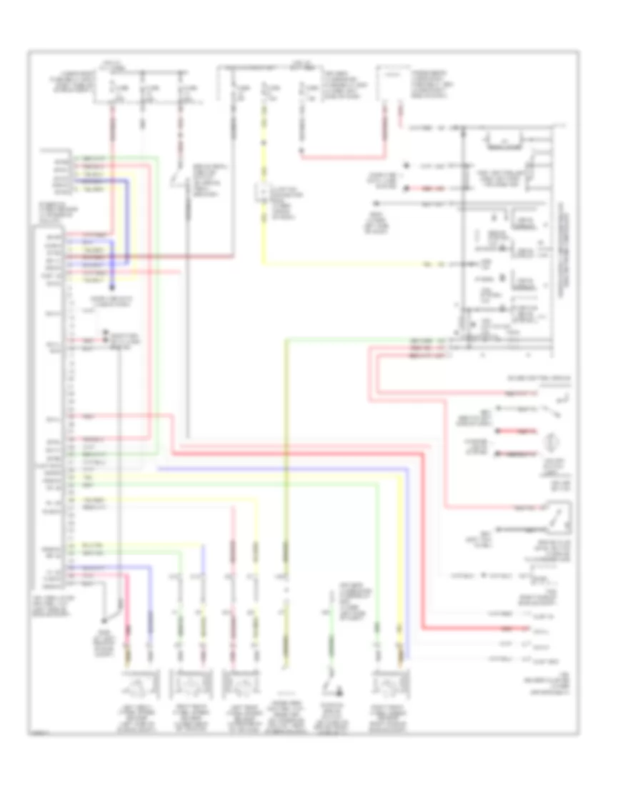
List of elements for Anti-lock Brakes Wiring Diagram for Honda Odyssey Touring 2007:
- (in brake fluid reservoir)
- (under
- +b-fsr
- +b-mr
- 5v regulator
- A21
- A23
- A24
- A27
- Abs ind
- Bksw
- Brake fluid level switch
- Brake pedal position switch (on brake pedal bracket)
- Brake system ind
- C10
- C12
- Can-h
- Can-l
- Clst gnd
- Clst ig
- Computer data lines system
- Diag-k
- Drive circuit
- Driver's seat)
- Driver's under-dash fuse/relay box (under left side of dash)
- E12
- E14
- Fast controller area network transceiver
- Fl +b
- Fl-gnd
- Fr +b
- Fr-gnd
- Fuse 15a
- Fuse 20a
- Fuse 30a
- Fuse 7.5a
- G302 (at left rear of engine compt)
- G401 (left kick panel)
- G501 (behind left side of dash)
- G502 (under left side of dash)
- Gauge control module
- Gnd
- Hot at all times
- Hot in on or start
- Ign in
- Immobilizer control unit- receiver (on steering column, near steering lock)
- Interior lights system
- Junction connector c503 (under middle of dash)
- Left front wheel speed sensor (left side of engine compt)
- Left rear wheel speed sensor (under rear of vehicle)
- Mr-gnd
- N30
- N34
- Parking brake switch (on parking brake pedal assembly)
- Passenger's under-dash fuse/relay box (under right side of dash)
- Pcm (right side of engine compt)
- Pnk
- Red
- Right front wheel speed sensor (right side of engine compt)
- Right rear wheel speed sensor (under rear of vehicle)
- Rl +b
- Rl-gnd
- Rr +b
- Rr-gnd
- S-gnd
- Steering angle sensor (in steering column)
- Stra
- Strb
- Strz
- Svcc
- Under-hood fuse/relay box (right side of engine compt)
- Vsa activation ind
- Vsa modulator control unit (left side of engine compt)
- Vsa off switch
- Vsa off switch light
- Vsa sensor cluster
- Vsa system ind
- Warning drive circuit
- X34
- X35
 English