STARTING/CHARGING
Charging Wiring Diagram for Honda Odyssey Touring 2007

List of elements for Charging Wiring Diagram for Honda Odyssey Touring 2007:
- (under left side of dash)
- A10
- A21
- A3 load output
- Alt c sig
- Alt fr sig
- Alt l sig
- Alternator
- Battery
- C42
- C43
- C44
- Charging system indicator
- Drive circuit
- Driver's under-dash fuse/relay box (under left side of dash)
- Eld in- put
- Eld unit
- Fuse 18 15a
- Fuse 21 7.5a
- G1 (at left front of engine compt)
- G202 (right side of engine compartment)
- G502
- Gauge control module
- Ground
- Hot in on or start
- Ignition input
- J/c c101 (right side of engine)
- J/c c503 (under middle of dash)
- Multi- fuse 22 120a
- Pcm (right side of engine compt)
- Pnk
- Power distribution system
- Sol in- put
- Starting circuit
- T101
- T102
- Transmission
- Under-hood fuse/relay box (right side of engine compt)
- X34
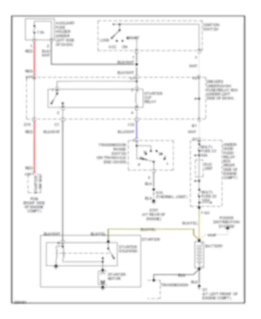
Starting Wiring Diagram for Honda Odyssey Touring 2007
List of elements for Starting Wiring Diagram for Honda Odyssey Touring 2007:
- 7.5a
- A31
- Acc
- Auxiliary fuse holder (under left side of dash)
- Battery
- D15
- Driver's under-dash fuse/relay box (under left side of dash)
- Eld unit
- G1 (at left front of engine compt)
- G101 (at rear of engine)
- Ignition switch
- Lock
- Multi- fuse 22 120a
- Multi- fuse 23 50a
- Pcm (right side of engine compt)
- Power distribution system
- Red
- Start
- Starter
- Starter cut relay
- Starter motor
- Starter solenoid
- Sw sig starter
- T101
- Transmission
- Transmission range switch (on transaxle end cover)
- Under- hood fuse/ relay box (right side of engine compt)
- X11
- X33