POWER DISTRIBUTION
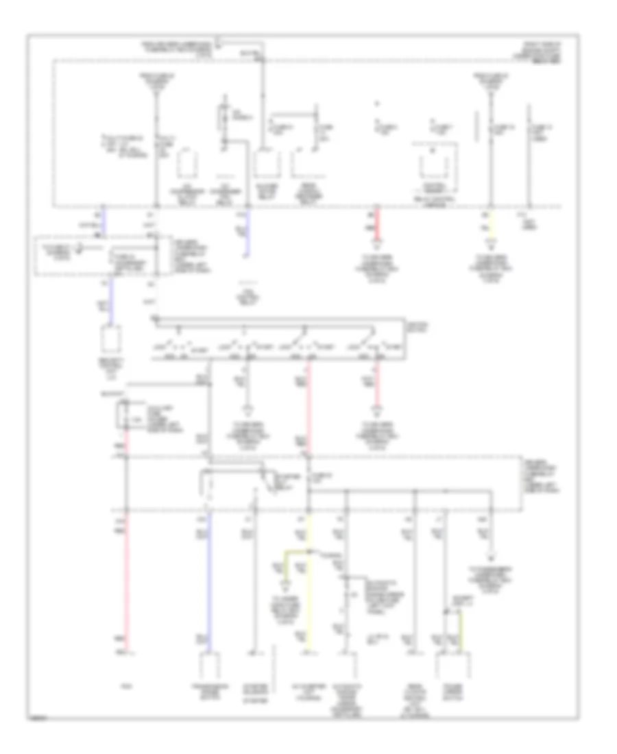
Power Distribution Wiring Diagram (1 of 6) for Honda Odyssey Touring 2007

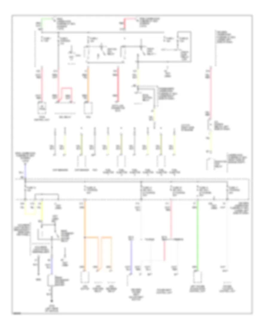
List of elements for Power Distribution Wiring Diagram (1 of 6) for Honda Odyssey Touring 2007:
- (not used)
- A/c compressor clutch relay
- A/c condenser fan relay
- A10
- Ac inverter unit
- Acm control relay
- Alternator
- Auxiliary under-hood fuse box (right rear of engine compt)
- Battery
- Eld unit
- Etcs control relay
- Fog light relay
- From fuse 32 (diagram 5 of 6)
- Front passenger's accessory power socket
- Fuse 1 (not used)
- Fuse 1 30a
- Fuse 10 (not used)
- Fuse 11 (res (dvd): ex-l & touring) 7.5a
- Fuse 11 30a
- Fuse 12 7.5a
- Fuse 19 30a
- Fuse 2 (not used)
- Fuse 2 40a
- Fuse 20 40a
- Fuse 3 15a
- Fuse 3 40a
- Fuse 4 (touring) 40a
- Fuse 4 20a
- Fuse 5 (accessory installed) 7.5a
- Fuse 5 (touring) 20a
- Fuse 6 (ex-l & touring) 15a
- Fuse 6 (touring) 20a
- Fuse 7 (touring) 10a
- Fuse 8 (ex, ex-l & touring) 20a
- Fuse 8 (ex-l & touring) 10a
- Fuse 9 (not used)
- Fuse 9 15a
- Fuse 9 30a
- G504 (behind right end of dash)
- Left power sliding door control unit
- Left sliding door lock relay
- Left sliding door unlock relay
- Micu-rear junction box (behind right rear side trim panel)
- Multi-fuse 120a
- Multi-fuse 70a
- Passenger's accessory power socket relay
- Passenger's under-dash fuse/relay box (under right side of dash)
- Power tailgate control unit
- Radiator fan relay
- Rear blower motor relay
- Rear controller & screen
- Red
- Right power sliding door control unit
- Seat heater relay
- Starter
- Starter solenoid
- Stereo amplifier
- T101
- T102
- To driver's under-dash fuse/relay box (diagram 3 of 6)
- To driver's under-dash fuse/relay box (diagram 6 of 6)
- To fuse 15 (diagram 2 of 6)
- To fuse 17 (diagram 5 of 6)
- To fuse 4 (diagram 5 of 6)
- To multi- fuse 23 (diagram 2 of 6)
- Trailer lighting control unit (accessory installed)
- Under-hood fuse/relay box (right side of engine compt)
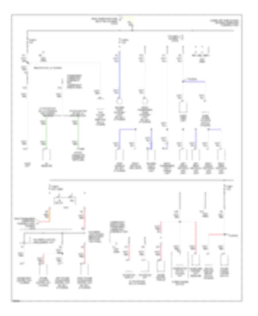
Power Distribution Wiring Diagram (2 of 6) for Honda Odyssey Touring 2007
List of elements for Power Distribution Wiring Diagram (2 of 6) for Honda Odyssey Touring 2007:
- (diagram 3 of 6)
- (lx) (ex, ex-l & touring)
- (not used)
- (right side of engine compt) under-hood fuse/ relay box
- 7.5a
- A/c compressor clutch relay
- A/c condenser fan relay
- A/c diode a
- A31
- Ac inverter unit (touring)
- Acc
- Automatic dimming inside mirror (accessory installed)
- Automatic dimming inside mirror in-line fuse (left kick panel)
- Auxiliary fuse holder (under left side of dash)
- Blower motor relay
- Control block
- D15
- Driver's under-dash fuse/relay box (under left side of dash)
- Except usa: lx
- F13
- F19
- Fan control relay
- From driver's under-dash m fuse/relay box (diagram 2 of 6)
- From fuse 20 (diagram 1 of 6)
- Fuse 10 (not used)
- Fuse 15 40a
- Fuse 21 40a
- Fuse 30 10a
- Fuse 30a
- Fuse 33 (accessory installed) 2a
- Fuse 7 7.5a
- Fuse 8 15a
- Ignition switch
- Lock
- Lx, ex & ex-l
- Multi- fuse 50a
- Multi-fuse 23 40a 50a
- N20
- Pcm
- Power mirror switch
- Rear climate control unit (ex, ex-l & touring)
- Rear window defogger relay
- Red
- Relay control module
- Security control unit (lx)
- Start
- Starter
- Starter cut relay
- Starter solenoid
- To driver's under-dash fuse/relay box
- To driver's under-dash fuse/relay box (diagram 4 of 6)
- To driver's under-dash fuse/relay box (diagram 5 of 6)
- To driver's under-dash fuse/relay box (diagram 6 of 6)
- To fuse 27 (diagram 5 of 6)
- To passenger's under-dash fuse/relay box (diagram 5 of 6)
- To under- hood fuse/ relay box (diagram 2 of 6)
- Touring
- Transmission range switch
- X11
- X33
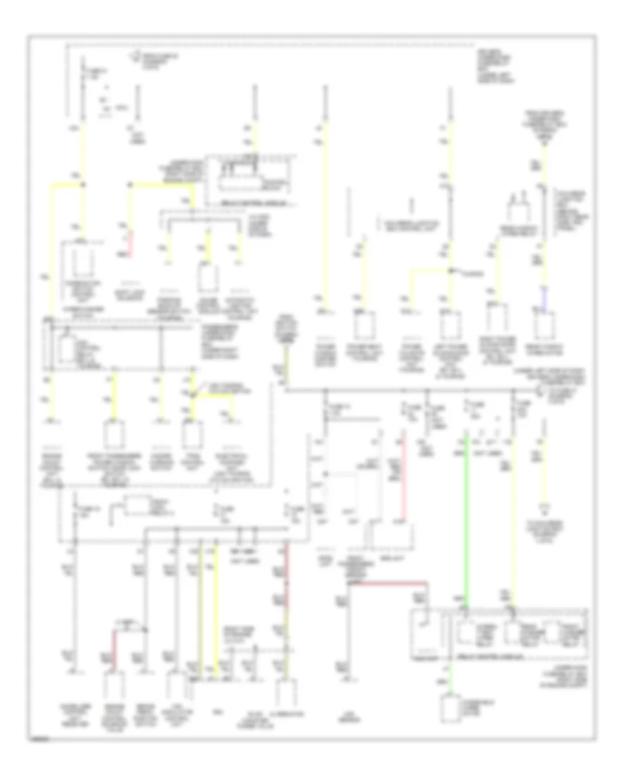
Power Distribution Wiring Diagram (3 of 6) for Honda Odyssey Touring 2007
List of elements for Power Distribution Wiring Diagram (3 of 6) for Honda Odyssey Touring 2007:
- (diagram 1 of 6)
- (not used)
- (under left side of dash) driver's under-dash fuse/relay box
- (under right side of dash) passenger's under-dash fuse/relay box
- +b dr lck
- 10a
- 7.5a
- A10
- A11
- A37
- Audio unit
- B10
- C699
- Cargo area light
- Combination switch control unit
- D10
- D11
- D12
- D13
- Driver's door courtesy light (ex, ex-l & touring)
- Driver's vanity mirror light
- Driving position memory switch (touring)
- Dvd player unit (res (dvd): ex-l & touring)
- E14
- From passenger's under-dash fuse/relay box f
- From under-hood fuse/ q relay box (diagram 2 of 6)
- Front individual map lights
- Front passenger's door courtesy light (ex, ex-l & touring)
- Front passenger's vanity mirror light
- Fuse 5
- Fuse 6
- Fuse 7
- Fuse 8
- Gauge control module
- Immobilizer control unit- receiver
- Inner power tailgate switch (touring)
- J11 (not used)
- Left middle individual map light
- Left power sliding door control unit (ex, ex-l & touring)
- Left rear individual map light
- Micu
- Micu-rear junction box (behind right rear side trim panel)
- Micu-rear junction box control unit
- N11
- N15
- Navigation display
- Navigation unit
- Option connector (accessory installed)
- Passenger's under-dash fuse/relay box (under right side of dash)
- Power seat control unit (touring)
- Power tailgate control unit (touring)
- Power window master switch
- Res (dvd): ex-l & touring
- Right middle individual map light
- Right power sliding door control unit (ex, ex-l & touring)
- Right rear individual map light
- Roof console (ex, ex-l & touring)
- To fuse 9 (diagram 5 of 6)
- Touring
- Vbu
- W/ navigation: ex-l & touring
- W/ navigation: ex-l & touring & usa touring: res (dvd)
- W/o navigation: ex, ex-l & ex-l res (dvd)
- Wiper/washer switch
- X22
- X35
- Xm receiver
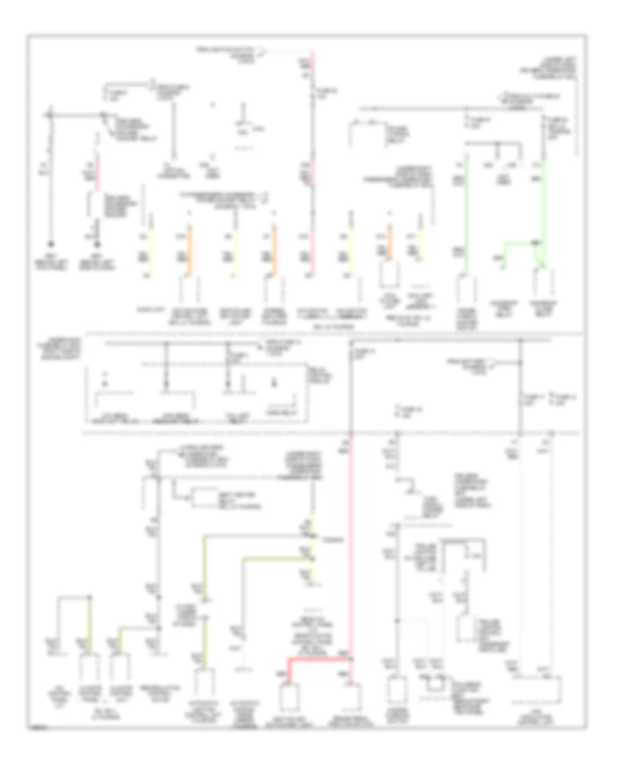
Power Distribution Wiring Diagram (4 of 6) for Honda Odyssey Touring 2007
List of elements for Power Distribution Wiring Diagram (4 of 6) for Honda Odyssey Touring 2007:
- (not
- (not used)
- (right side of engine) j/c c101
- (under left side of dash) driver's under-dash fuse/relay box
- 10a
- 15a
- 20a 10a
- 30a
- 7.5a
- A12
- A14
- A17
- A18
- A35
- Acm control relay (ex-l & touring)
- Alternator
- Automatic lighting control unit (touring)
- B42
- Brake pedal position switch
- C14
- Combination switch control unit
- Control block
- Driver's under-dash fuse/relay box (under left side of dash)
- Eld unit
- Electrical compass unit (usa touring w/o navigation)
- Engine mount control solenoid valve
- Engine mount control unit (ex-l & touring)
- Evap canister purge valve
- From driver's under-dash fuse/relay box (diagram 4 of 6)
- From fuse 20 (diagram 4 of 6)
- From ignition switch (diagram 2 of 6)
- Front passenger's power window switch/ door lock switch (ex, ex-l & touring)
- Front passenger's weight sensor unit
- Front washer motor relay
- Fuse
- Fuse 10
- Fuse 19
- Fuse 21
- Gauge control module
- Hazard warning switch
- Ig1
- Immobilizer control unit- receiver
- Intermi- ttent wiper relay
- J/c c503 (under middle of dash)
- J10
- Left power sliding door control unit (ex, ex-l & touring)
- Lx & ex
- Maf sensor
- Micu
- Micu-rear junction box (behind right rear side trim panel)
- Micu-rear junction box control unit
- N29
- N41
- Opds unit
- Parking/ back-up sensor switch (touring)
- Passenger's under-dash fuse/relay box (under right side of dash)
- Pcm
- Pgm-fi main relay 2
- Power seat control unit (touring)
- Power tailgate control unit (touring)
- Power window master switch
- Rear washer motor relay
- Rear window wiper motor
- Rear window wiper relay
- Red
- Relay control module
- Right power sliding door control unit (ex, ex-l & touring)
- Shift lock solenoid
- Srs unit
- To fuse 21 (diagram 4 of 6)
- To micu-rear junction box (diagram 4 of 6)
- Touring
- Tpms control unit
- Under-hood fuse/relay box (right side of engine compt)
- Usa touring w/o navigation
- Used)
- Vsa modulator control unit
- Windshield wiper motor
- Wiper/washer switch
- X16
- X17
- X20
- X34
- X38
Power Distribution Wiring Diagram (5 of 6) for Honda Odyssey Touring 2007
List of elements for Power Distribution Wiring Diagram (5 of 6) for Honda Odyssey Touring 2007:
- (not used)
- (option connector)
- (under left side of dash) driver's under-dash fuse/relay box
- (under right side of dash) passenger's under-dash fuse/relay box
- 10a
- 15a
- 20a
- 30a
- 7.5a
- A/c control panel (lx)
- A11
- Acc
- Active noise control unit (ex-l & touring)
- Audio unit
- Automatic dimming inside mirror (touring)
- Automatic lighting control unit (touring)
- Auxiliary jack assembly
- Brake pedal position switch
- Climate control panel
- Climate control unit
- D14
- D15
- D16
- D17
- Driver's accessory power socket
- Driver's accessory power socket relay
- Driver's under-dash fuse/relay box (under left side of dash)
- Dvd player unit
- Ex, ex-l & touring
- Ex-l & touring
- From battery (diagram 1 of 6)
- From driver's under-dash fuse/relay box (diagram 2 of 6)
- From fuse 12 (diagram 1 of 6)
- From fuse 6 (diagram 3 of 6)
- From ignition switch (diagram 2 of 6)
- From multi-fuse 23 (diagram 2 of 6)
- Fuse 13 20a
- Fuse 16
- Fuse 17
- Fuse 18
- Fuse 27
- Fuse 28 (ex-l & touring) 20a
- Fuse 32
- Fuse 4 15a
- Fuse 9
- G501 (behind left side of dash)
- G601 (behind left kick panel)
- Hazard warning switch
- High beam headlight relay
- Horn relay
- Ignition key switch/key light
- J/c c503 (under middle of dash)
- Low beam headlight relay
- Micu
- Micu-rear junction box (behind right rear side trim panel)
- Moonroof close relay
- Moonroof open relay
- N36
- N39
- N45
- Navigation display
- Navigation unit
- Power window master switch
- Power window relay
- Rear a/c control panel (lx) rear climate control panel (ex, ex-l & touring)
- Recirculation control motor
- Red
- Relay control module
- Res (dvd): ex-l & touring
- Seat heater relay (ex-l & touring)
- Stereo amplifier (touring)
- Taillight relay
- To passenger's accessory power socket relay (diagram 1 of 6)
- Touring
- Trailer lighting control unit (accessory installed)
- Trailer lighting in-line fuse (left "d" pillar)
- Turn signal/ hazard relay
- Under-hood fuse/relay box (right side of engine compt)
- Vsa modulator control unit
- X14
- X24
- X39
Power Distribution Wiring Diagram (6 of 6) for Honda Odyssey Touring 2007
List of elements for Power Distribution Wiring Diagram (6 of 6) for Honda Odyssey Touring 2007:
- (not used)
- +b tpms
- 15a
- 7.5a
- A/c diode b (below left side of dash)
- Aps forward relay
- Aps reverse relay
- Aps switch
- B12
- Ckp sensors
- Cmp sensor
- D10
- D14
- D16
- Data link connector (dlc)
- Day lt
- Driver's power seat adjustment switch
- Driver's under-dash fuse/relay box (under left side of dash)
- Drl relay
- Etcs control relay
- Ex & ex-l
- F11
- F13
- From under-hood fuse/relay box (diagram 1 of 6)
- From under-hood fuse/relay box (diagram 2 of 6)
- Fuel injector
- Fuse 1 7.5a
- Fuse 12
- Fuse 13 (ex, ex-l & touring) 20a
- Fuse 14 (ex, ex-l & touring) 20a
- Fuse 15 (touring) 20a
- Fuse 16 (ex, ex-l & touring) 20a
- Fuse 17 (touring) 20a
- Fuse 2
- Fuse 23
- Fuse 3 (canada) 10a
- Fuse 4
- G652
- G702 (left rear of vehicle)
- Ignition coil relay
- J/c c101 (right side of engine)
- Left power sliding door control unit
- Micu
- Micu-rear junction box (behind right rear side trim panel)
- Micu-rear junction box control unit
- N10
- N40
- Passenger's under-dash fuse/relay box (under right side of dash)
- Pcm
- Pgm-fi main relay 1
- Pgm-fi sub- relay (laf)
- Power seat control unit
- Power tailgate control unit
- Radiator fan relay
- Rear accessory power socket
- Rear accessory power socket relay
- Red
- Touring
- Tpms control unit
- Under-hood fuse/relay box (right side of engine compt)
- X12
- X15
- X23
- X26
- X31