ENGINE PERFORMANCE
3.5L
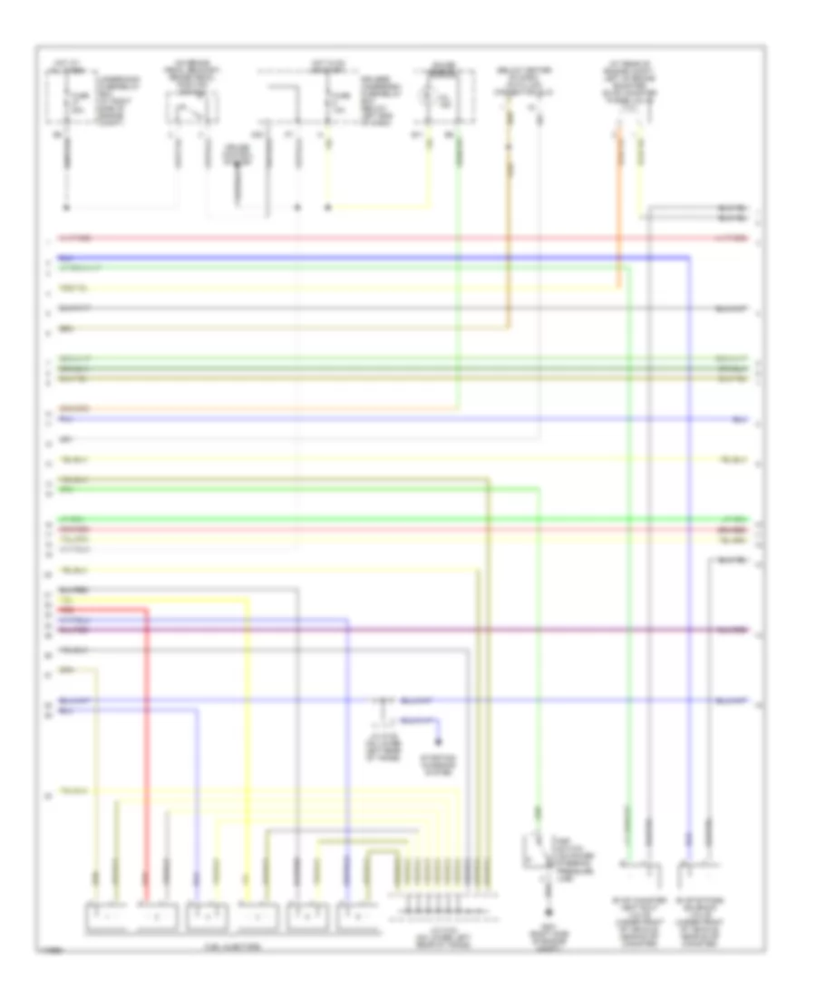
3.5L, Engine Performance Wiring Diagram (1 of 6) for Honda Odyssey EX 2004

List of elements for 3.5L, Engine Performance Wiring Diagram (1 of 6) for Honda Odyssey EX 2004:
- (below left side of dash) pgm-fi main relay
- 2wbs
- 4th clutch pressure switch (on left side of transmission)
- A/c system
- A/t clutch pressure control solenoid valve a (on top of transmission)
- A/t clutch pressure control solenoid valve b (on top of transmission)
- A/t clutch pressure control solenoid valve c (on left front of transmission)
- A10
- A11
- A12
- A13
- A14
- A15
- A16
- A17
- A18
- A19
- A20
- A21
- A22
- A23
- A24
- A25
- A26
- A27
- A28
- A29
- A30
- A31
- A32
- Acc
- Acs
- Atpnp
- B10
- B11
- B12
- B13
- B14
- B15
- B16
- B17
- B18
- B19
- B20
- B21
- B22
- B23
- B24
- B25
- Bksw
- C101
- Ccs
- Cooling fans system
- Cruise control system
- Dind
- Driver's underdash fuse/relay box (below left end of dash)
- Ect out
- Egr
- Eld
- Fanc
- Ftp
- Fuse 15a
- Fuse 7.5a
- G101 (left side of engine compt)
- Hot at all times
- Hot in on or start
- Hot in start
- Iac valve (near throttle body)
- Iacv
- Igp1
- Igp2
- Ilu
- Imofpr
- Inj1
- Inj2
- Inj3
- Inj4
- Inj5
- Inj6
- J/c c105 (on lower left rear of trans)
- J/c c107 (below center of dash)
- K-line
- Lg1
- Lg2
- Lsa+
- Lsa-
- Lsb+
- Lsb-
- Lsc+
- Lsc-
- Mcs
- Mil
- Nep
- Op4sw
- Passenger's underdash fuse/relay box (behind right kick panel)
- Pcm (behind lower center of dash)
- Pcs
- Pg1
- Pg2
- Pspsw
- Red
- Scs
- Shift interlock system
- Sho2s
- So2shtc
- Stsw
- Underhood fuse/relay box (at right side of engine compt)
- Vbu
- Vssout
- Vsv
- Vtec solenoid valve (on lower front of engine, near oil filter)
- Vtsol
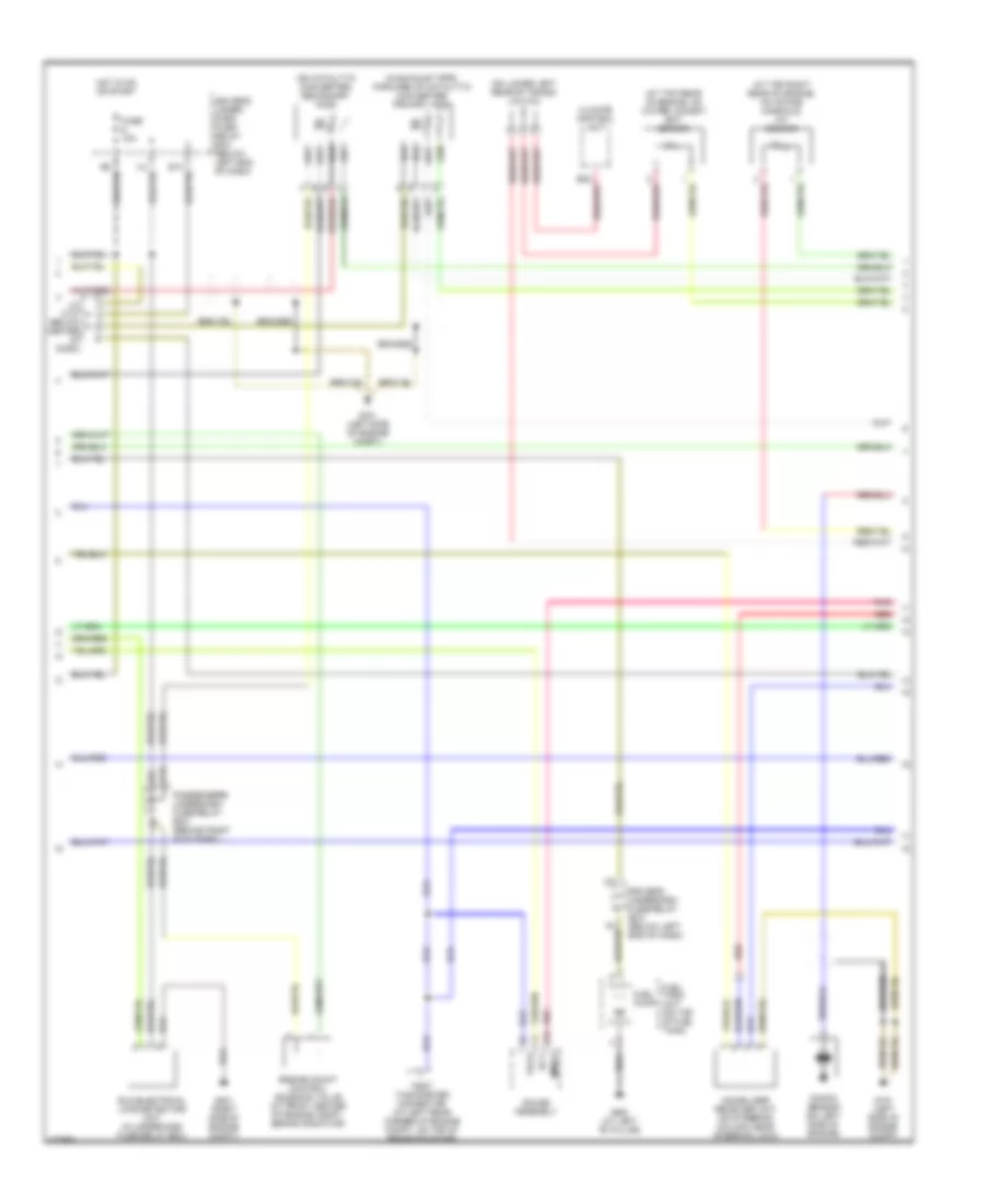
3.5L, Engine Performance Wiring Diagram (2 of 6) for Honda Odyssey EX 2004
List of elements for 3.5L, Engine Performance Wiring Diagram (2 of 6) for Honda Odyssey EX 2004:
- (at rear of engine compt, left of brake booster) evap canister purge valve
- (below center of dash) data link connector (dlc)
- (on brake pedal bracket) brake pedal position switch
- Cruise control system
- Driver's underdash fuse/relay box (below left end of dash)
- Evap bypass solenoid valve (under front of vehicle, near evap canister)
- Evap canister vent shut valve (under front of vehicle, near evap canister)
- Fuel injectors
- Fuse 10a
- Fuse 20a
- G201 (right side of engine compt)
- Gauge assembly
- Hot at all times
- Hot in on or start
- J/c c104 (on lower left rear of trans)
- J/c c105 (on lower left rear of trans)
- Mil ind
- Psp switch (on power steering pressure line)
- Red
- Starting/ charging system
- Underhood fuse/relay box (at right side of engine compt)
3.5L, Engine Performance Wiring Diagram (3 of 6) for Honda Odyssey EX 2004
List of elements for 3.5L, Engine Performance Wiring Diagram (3 of 6) for Honda Odyssey EX 2004:
- (at top rear of engine, on water jacket) ect sensor
- (at top right rear of engine, on intake manifold) iat sensor
- (in exhaust pipe, forward of catalytic converter) primary ho2s
- (on catalytic converter) secondary ho2s
- (on lower left rear of trans) j/c c104
- B19
- Braided
- C10
- Climate control unit
- Driver's under- dash fuse/ relay box (below left end of dash)
- Driver's underdash fuse/relay box (below left end of dash)
- Ect
- Eld (electrical load detector) unit (in underhood fuse/relay box)
- Engine mount control solenoid valve (at front center of engine compt, behind radiator)
- Fuel pump
- Fuel tank unit (on top of fuel tank)
- Fuse 15a
- G101 (left side of engine compt)
- G201 (right side of engine compt)
- G551 (at left "b" pillar)
- Gauge assembly
- Hot in on or start
- I12
- Immob
- Immobilizer receiver unit (on steering column, near steering lock)
- J/c c107 (below center of dash)
- Knock sensor (on left side of engine)
- Passenger's underdash fuse/relay box (behind right kick panel)
- Pnk
- Red
- Tach
- Test tachometer connector (at left rear corner of engine compt, on top of brake booster)
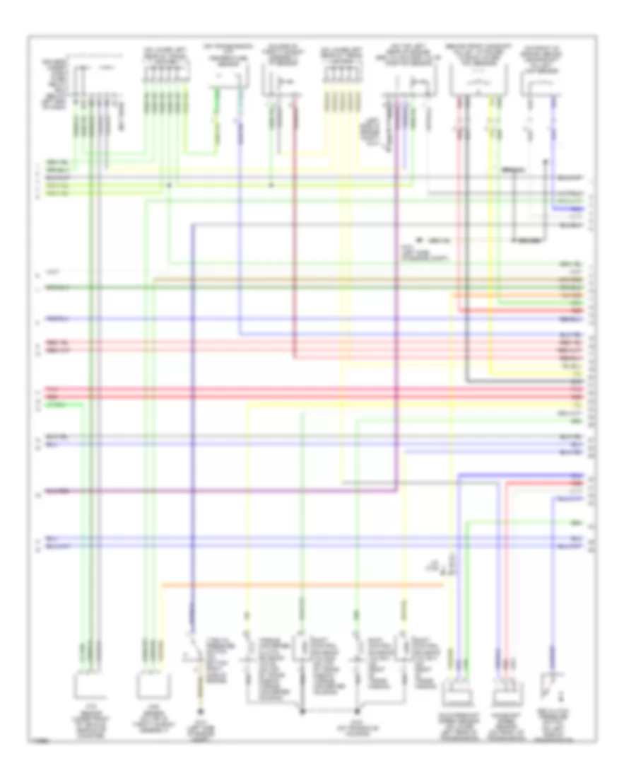
3.5L, Engine Performance Wiring Diagram (4 of 6) for Honda Odyssey EX 2004
List of elements for 3.5L, Engine Performance Wiring Diagram (4 of 6) for Honda Odyssey EX 2004:
- (behind front camshaft pulley, attached to back cover) tdc sensors
- (left side of engine compt)
- (not used)
- (on front of engine, behind crankshaft pulley) ckp sensor
- (on lower left rear of trans) j/c c104
- (on lower left rear of trans) j/c c105
- (on side of throttle body assembly) tp sensor
- (on top left rear of engine) egr valve & egr valve position sensor
- (on transmission) atf temperature sensor
- 3rd clutch pressure switch (on left side of transmission)
- Braided
- Countershaft speed sensor (on lower left rear of transmission)
- Driver's under- dash fuse/ relay box (below left end of dash)
- E14
- Ftp sensor (under front of vehicle, near evap canister)
- G101
- G101 (left side of engine compt)
- G151 (on transaxle housing)
- I17
- J/c c105
- Mainshaft speed sensor (on front of transmission)
- Map sensor (on top of throttle body assembly)
- Pnk
- Red
- Shift control solenoid valve a (on front of trans- mission)
- Shift control solenoid valve b (on top of trans- mission torque converter housing)
- Shift control solenoid valve c (on front of trans- mission)
- Torque converter clutch solenoid valve (on top of trans- mission torque converter housing)
- Vtec oil pressure switch (on bottom right side of engine)
3.5L, Engine Performance Wiring Diagram (5 of 6) for Honda Odyssey EX 2004
List of elements for 3.5L, Engine Performance Wiring Diagram (5 of 6) for Honda Odyssey EX 2004:
- (w/ dvd: behind right kick panel) (w/o dvd: behind right side of glove box)
- A/t gear position indicator
- B10 red
- C6 red
- Cruise control system
- Dimming circuit
- Driver's underdash fuse/relay box (below left end of dash)
- Fuse 10a
- G101 (left side of engine compt)
- G503
- Gauge assembly
- Hot in on or start
- Interior lights system
- Pnk
- Power distribution system
- Red
- Reverse relay
- Transmission range switch (on transaxle end cover)
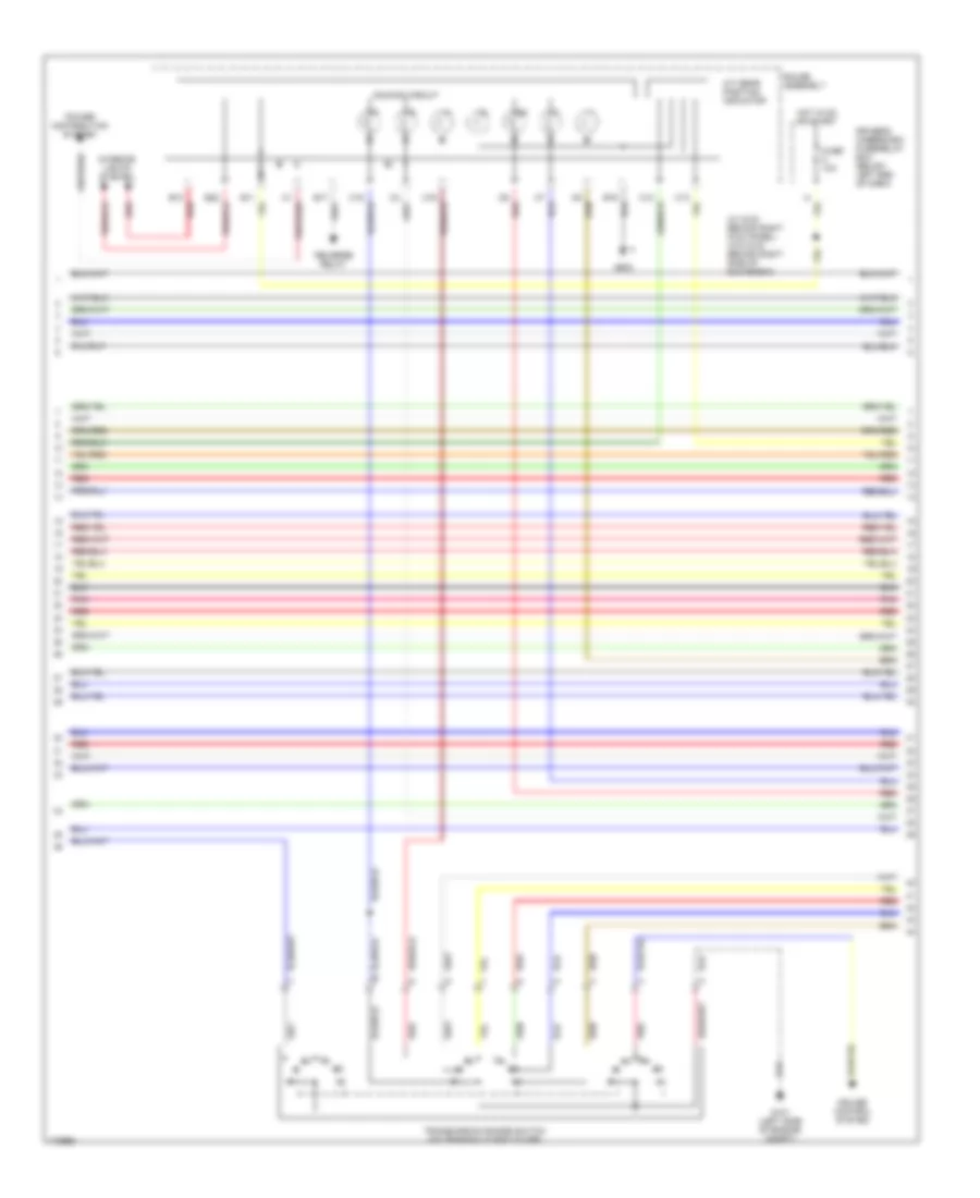
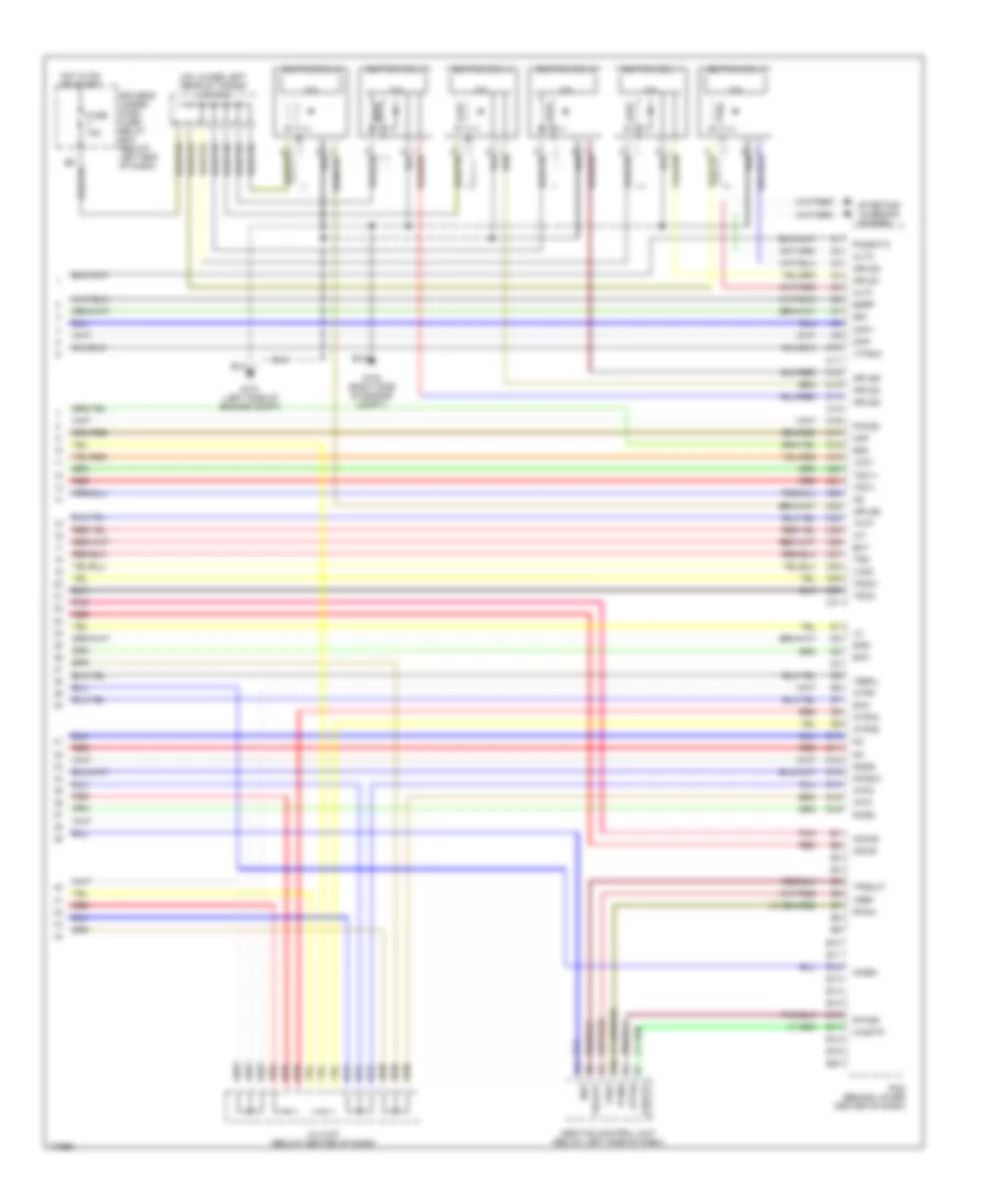
3.5L, Engine Performance Wiring Diagram (6 of 6) for Honda Odyssey EX 2004
List of elements for 3.5L, Engine Performance Wiring Diagram (6 of 6) for Honda Odyssey EX 2004:
- (on lower left rear of trans) j/c c104
- Abs/tcs control unit (below left side of dash)
- Altc
- Altf
- Atp1
- Atp2
- Atpd3
- Atpd5
- Atpr
- Atsftp
- B10
- B11
- C10
- C11
- C12
- C13
- C14
- C15
- C16
- C17
- C18
- C19
- C20
- C21
- C22
- C23
- C24
- C25
- C26
- C27
- C28
- C29
- C30
- C31
- Ckp+
- Ckp-
- D10
- D11
- D12
- D13
- D14
- D15
- D16
- Driver's under- dash fuse/ relay box (below left end of dash)
- E10
- E11
- E12
- E13
- E14
- E15
- E16
- E17
- E18
- E19
- E20
- Ect
- Egrp
- Fptdr
- Fuse 15a
- G101 (left side of engine compt)
- G102 (right side of engine compt)
- Hot in on or start
- Iat
- Icm
- Ignition coil 1
- Ignition coil 2
- Ignition coil 3
- Ignition coil 4
- Ignition coil 5
- Ignition coil 6
- Igpls1
- Igpls2
- Igpls3
- Igpls4
- Igpls5
- Igpls6
- Imocd
- Imoen
- Imoind
- J/c c107 (below center of dash)
- Map
- Ncsg
- Nep
- Nmsg
- Op3sw
- Pcm (behind lower center of dash)
- Pfinh
- Pho2s
- Pnk
- Po2shtc
- Red
- Sg1
- Sg2
- Sha
- Shb
- Shc
- Starting/ charging system
- Tatf
- Tdc1+
- Tdc1-
- Tdc2+
- Tdc2-
- Thlout
- Tps
- Tpsout
- Vbsol
- Vcc1
- Vcc2
- Vref
- Vtpsw