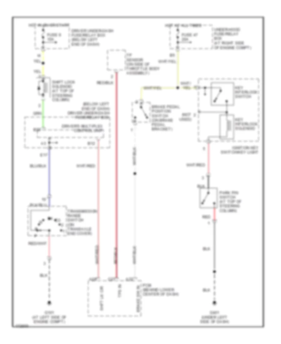
SHIFT INTERLOCK
Shift Interlock Wiring Diagram for Honda Odyssey EX 2004
List of elements for Shift Interlock Wiring Diagram for Honda Odyssey EX 2004:
- (below left end of dash) driver under-dash fuse/relay box
- (not
- A28
- A32
- B12
- B22
- Brake pedal position switch (on brake pedal bracket)
- Brake sw in
- C27
- Driver under-dash fuse/relay box (below left end of dash)
- Driver's multiplex control unit
- E17
- Fuse 47 20a
- Fuse 9 10a
- G101 (at left side of engine compt)
- G401 (under left side of dash)
- Hot at all times
- Hot in on or start
- Ignition key switch/key light
- Key interlock solenoid
- Key interlock switch
- Park pin switch (at top of steering column)
- Pcm (behind lower center of dash)
- Red
- Shft lk cir
- Shift lock solenoid (at top of steering column)
- Tp sensor (on side of throttle body assembly)
- Tps in
- Transmission range switch (on transaxle end cover)
- Under-hood fuse/relay box (at right side of engine compt)
- Used)
 English