STARTING/CHARGING
Charging Wiring Diagram for Honda Odyssey EX 2004

List of elements for Charging Wiring Diagram for Honda Odyssey EX 2004:
- A30
- Alt ctrl sig
- Alt fr sig
- Alternator
- Battery
- Charge system indicator light
- Driver's multiplex control unit (in driver under-dash fuse/relay box)
- Driver's under- dash fuse/ relay box (below left end of dash)
- E13
- Eld in- put
- Eld unit
- Engine controls system
- Fuse 41 120a
- Fuse 6 15a
- G1 (at left side of engine compt)
- G201 (at right side of engine compt)
- Gauge assembly
- Ground
- Hot in on or start
- I12
- Ignition input
- J/c c105 (at left side of engine compt)
- Load output
- Navigation unit
- Passenger's under-dash fuse/relay box (behind right kick panel)
- Pcm (behind lower center of dash)
- Power distribution system
- Starting circuit
- T101
- T102
- Transmission
- Under-hood fuse/relay box (at right side of engine compt)
- W/ navigation
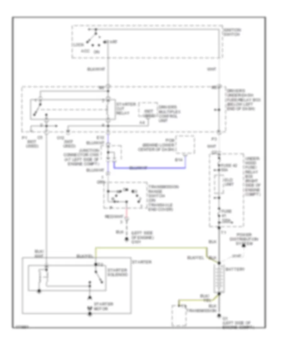
Starting Wiring Diagram for Honda Odyssey EX 2004
List of elements for Starting Wiring Diagram for Honda Odyssey EX 2004:
- (left side of engine) g101
- (not used)
- Acc
- B14
- Battery
- Driver's multiplex control unit
- Driver's under-dash fuse/relay box (below left end of dash)
- E12
- Eld unit
- Fuse 120a
- Fuse 42 50a
- G1 (left side of engine compt)
- Ignition switch
- Junction connector c105 (at left side of engine compt)
- Lock
- O12
- Pcm (behind lower center of dash)
- Power distribution system
- Start
- Starter
- Starter cut relay
- Starter motor
- Starter solenoid
- Transmission
- Transmission range switch (on transaxle end cover)
- Under- hood fuse/ relay box (right side of engine compt)