AIR CONDITIONING
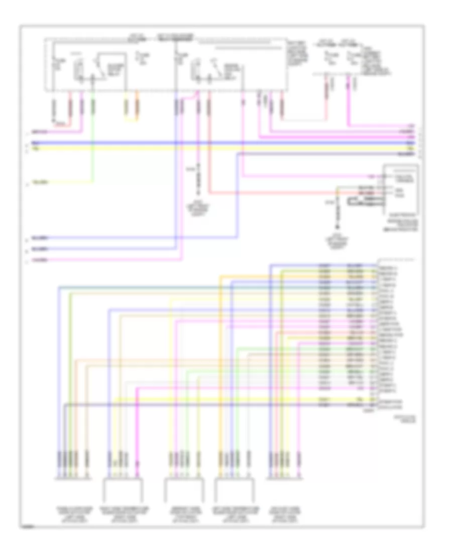
Automatic A/C Wiring Diagram (1 of 3) for Ford Escape S 2013

List of elements for Automatic A/C Wiring Diagram (1 of 3) for Ford Escape S 2013:
- (left kick panel) g205
- (left side of hvac unit) evaporator discharge air temperature sensor
- (main wiring assembly, in breakout to in-vehicle temperature/ humidity sensor) s215
- (main wiring assembly, near breakout to passenger air bag
- (right kick panel) g206
- (top center of dash) autolamp/sunload sensor
- Ambient lt
- Aspirator gnd
- Blower ctrl
- Blower diode (left side of engine compt)
- Blower motor
- Blower motor control module (on blower motor)
- Bmrc
- Body control module (bcm) (right side of dash)
- C213
- C219
- C2280a
- C2280b
- C2280c
- C2280f
- C228b
- C297a
- C297b
- Ch123
- Ch402
- Computer data lines system
- Datc hvac module
- Deactivation (pad) indicator)
- Disc floor l snsr
- Disc floor r snsr
- Disc panel l snsr
- Disc panel r snsr
- Evap temp snsr
- Fuse 10a
- Fuse 7.5a
- Gd133
- Gd138
- Gnd
- Grille shutter actuator (behind right side of front grille)
- Hot at all times
- Hot w/ ignition relay energized
- Humidity snsr
- In car snsr +
- In car snsr -
- In-vehicle temperature/ humidity sensor (left side of dash)
- L sunl snsr
- Left floor discharge air temperature sensor (lower left center of dash)
- Left panel discharge air temperature sensor (left center of dash)
- Lin
- Micro
- Motor+
- Motor-
- Ms can +
- Ms can -
- Ms can+
- Ms can-
- Nca
- Ptc htr ctrl
- R sunl snsr
- Rh103
- Rh104
- Rh105
- Rh119
- Right floor discharge air temperature sensor (lower right center of dash)
- Right panel discharge air temperature sensor (right center of dash)
- S218
- S221
- S241
- S247 (main wiring assembly, near breakout to body control module (bcm))
- S249
- Sbp71
- Sig rtn
- Snsr
- Snsr gnd
- V batt
- Vdb06
- Vdb07
- Vh101
- Vh406
- Vh409
- Vh410
- Vh411
- Vh412
- Vh413
- Vh414
- Vh416
- Vh417
- Vlf14
- Vpwr
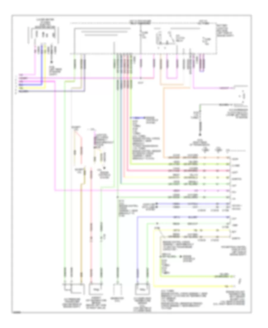
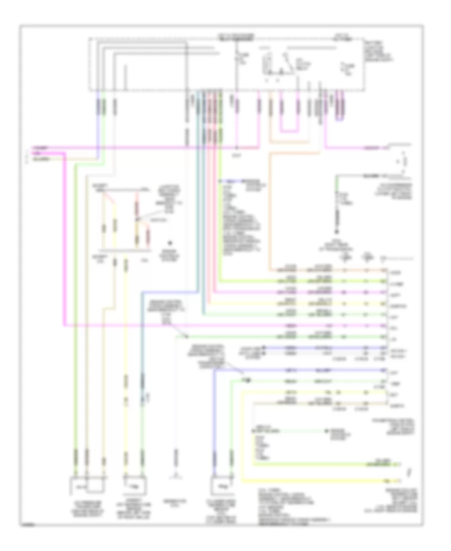
Automatic A/C Wiring Diagram (2 of 3) for Ford Escape S 2013
List of elements for Automatic A/C Wiring Diagram (2 of 3) for Ford Escape S 2013:
- Air inlet mode door actuator (right side of hvac unit)
- Battery junction box (bjb) (left side of engine compt)
- Blower motor relay
- C1035c
- C1617e
- C1617h
- C228a
- Ch201
- Ch202
- Ch203
- Ch204
- Ch205
- Ch206
- Ch207
- Ch208
- Ch209
- Ch210
- Ch211
- Ch212
- Ch213
- Ch214
- Ch215
- Ch227
- Ch228
- Ch229
- Ch230
- Ch231
- Ch237
- Ch238
- Ch239
- Ch240
- Ch241
- Datc hvac module
- Defr a
- Defr b
- Defr c
- Defr d
- Defr pwr
- Defrost mode door actuator (top front of hvac unit)
- Electronics
- Engine cooling fan motor (behind radiator)
- Engine cooling fan relay
- Fan ctrl variable
- Fuse 40a
- Fuse 50a
- Fuse 5a
- Fuse 80a
- G107 (left front of engine compt)
- Gnd
- High current battery junction box (bjb) (left side of engine compt)
- Hot at all times
- Hot w/ pcm power relay energized
- Left side temperature blend door actuator (left side of hvac unit)
- Ltemp a
- Ltemp b
- Ltemp c
- Ltemp d
- Ltemp pwr
- Nca
- Pa/fl a
- Pa/fl b
- Pa/fl c
- Pa/fl d
- Pa/fla pwr
- Panel/floor mode door actuator (left side of hvac unit)
- Pwr
- Recirc a
- Recirc b
- Recirc c
- Recirc d
- Recirc pwr
- Right side temperature blend door actuator (right side of hvac unit)
- Rtemp a
- Rtemp b
- Rtemp c
- Rtemp d
- Rtemp pwr
- S144
- S148
- S149
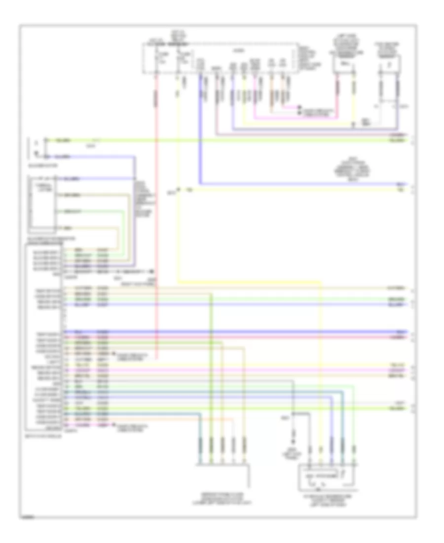
Automatic A/C Wiring Diagram (3 of 3) for Ford Escape S 2013
List of elements for Automatic A/C Wiring Diagram (3 of 3) for Ford Escape S 2013:
- (2.0l turbo: engine control wiring assembly, near breakout to intake air temperature (iat) sensor) (1.6l turbo: engine control sensor extension wiring assembly, near breakout to c1026)
- (lower center of dash) electric booster heater
- 1.6l turbo
- 2.0l turbo
- 2.5l
- A/c clutch relay
- A/c compressor clutch field coil (lower left front of engine)
- A/c pressure transducer (center rear of engine compt)
- Aat
- Accr
- Acpt
- Ambient air temperature sensor (behind left side of front grille)
- Battery junction box (bjb) (left side of engine compt)
- C-vref
- C1035c
- C134
- C1381b
- C1381e
- C1551b
- C1551e
- C175b
- C175e
- C2603a
- C2603b
- C2603c
- Ch109 (or ch302)
- Cht
- Computer data lines system
- Cylinder head temperature sensor (2.5l) (top center of cylinder head)
- Ect
- Engine control wiring assembly, near breakout to ignition transformer capacitor 1
- Engine controls system
- Engine coolant temperature (ect) sensor (except 2.5l) (1.6l: rear of engine) (2.0l: right rear of engine)
- Except 2.5l
- Fcv
- Fuse 10a
- Fuse 15a
- G104 (right rear of transmission)
- G106 (left rear of engine compt)
- Generator (2.5l)
- Gnd
- Hot at all times
- Hot w/ pcm power relay energized
- Hs can +
- Hs can -
- Ign
- Le424 (or lh108)
- Lin
- Powertrain control module (pcm) (left side of engine compt)
- Pwm
- Re405
- Re407 (or rh107)
- Re454 (or re329)
- S105 (2.0l turbo) s129 (1.6l turbo) (2.0l turbo: engine control wiring assembly, near breakout to 6f35 transmission) (1.6l turbo: engine control sensor extension wiring assembly, near breakout to g104)
- S108 (2.0l turbo) s123 (1.6l turbo)
- S115 (2.5l) (engine control wiring assembly, near breakout to c145)
- S125 (1.6l turbo)
- S147
- S176
- Sigrtn
- Sigrtnc
- Vdb04
- Vdb05
- Vdn06 (or vdc46)
- Ve203
- Ve712
- Ve716
- Ve750 (or vh407)
- Vh443 (or vh442)
- Vpwr
- Vref
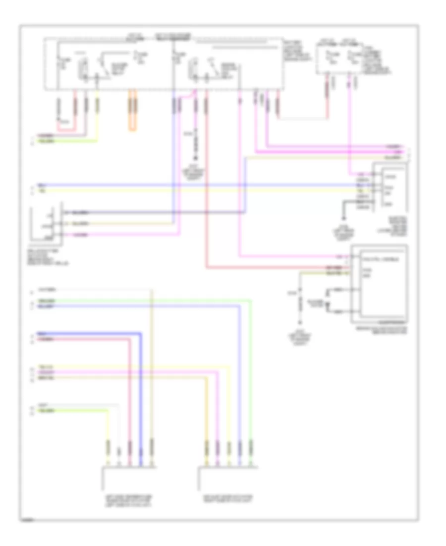
Manual A/C Wiring Diagram (1 of 3) for Ford Escape S 2013
List of elements for Manual A/C Wiring Diagram (1 of 3) for Ford Escape S 2013:
- (left side of hvac unit) evaporator discharge air temperature sensor
- (top center of dash) autolamp sensor
- Blower motor
- Blower motor resistor (on blower motor)
- Blower spd 1
- Blower spd 2
- Blower spd 3
- Blower spd 4
- Bmrc
- Body control module (bcm) (right side of dash)
- C213
- C219
- C2280a
- C2280b
- C2280c
- C2280f
- C2357a
- C2357b
- Ch123
- Ch201
- Ch202
- Ch203
- Ch204
- Ch205
- Ch206
- Ch207
- Ch208
- Ch209
- Ch210
- Ch232
- Ch233
- Ch234
- Ch235
- Ch236
- Ch403
- Ch427
- Ch428
- Ch429
- Chp01
- Computer data lines system
- Defrost/panel/floor mode door actuator (lower left side of hvac unit)
- Emtc hvac module
- Evap temp snsr
- Fuse 10a
- Fuse 7.5a
- G205 (left kick panel)
- G206 (right kick panel)
- Gd133
- Gd138
- Gnd
- Hot at all times
- Hot w/ ignition relay energized
- Humidity snsr
- In car snsr +
- In car snsr -
- In-vehicle temperature/ humidity sensor (left side of dash)
- Micro
- Mode door a
- Mode door b
- Mode door c
- Mode door d
- Mode dr pwr
- Ms can +
- Ms can -
- Ms can+
- Ms can-
- Ptc htr ctrl
- Recirc dr a
- Recirc dr b
- Recirc dr c
- Recirc dr d
- Recirc dr pwr
- Rh105
- Rh119
- S216 (main wiring assembly, near breakout to blower motor)
- S218
- S221
- S241
- S247 (main wiring assembly, near breakout to body control module (bcm))
- Sbp71
- Sig rtn
- Snsr
- Temp door a
- Temp door b
- Temp door c
- Temp door d
- Temp dr pwr
- Thermal limiter
- V batt
- Vdb06
- Vdb07
- Vh406
- Vh413
- Vh414
- Vlf14
- Vpwr
Manual A/C Wiring Diagram (2 of 3) for Ford Escape S 2013
List of elements for Manual A/C Wiring Diagram (2 of 3) for Ford Escape S 2013:
- Air inlet door actuator (right side of hvac unit)
- Battery junction box (bjb) (left side of engine compt)
- Blower motor
- Blower motor relay
- C1035c
- C1617e
- C1617h
- C2603a
- C2603b
- C2603c
- Electric booster heater (lower center of dash)
- Electronics
- Engine cooling fan motor (behind radiator)
- Engine cooling fan relay
- Fan ctrl variable
- Fuse 40a
- Fuse 50a
- Fuse 5a
- Fuse 80a
- G106 (left rear of engine compt)
- G107 (left front of engine compt)
- Gnd
- Grille shutter actuator (behind right side of front grille)
- High current battery junction box (bjb) (left side of engine compt)
- Hot at all times
- Hot w/ pcm power relay energized
- Ign
- Left side temperature blend door actuator (left side of hvac unit)
- Lin
- Nca
- Pwm
- Pwr
- S144
- S148
- S149
- Vpwr
Manual A/C Wiring Diagram (3 of 3) for Ford Escape S 2013
List of elements for Manual A/C Wiring Diagram (3 of 3) for Ford Escape S 2013:
- (2.0l turbo: engine control wiring assembly, near breakout to intake air temperature (iat) sensor) (1.6l turbo: engine control sensor extension wiring assembly, near breakout to c1026)
- (2.5l) s115
- (engine control wiring assembly, near breakout to c145)
- (engine control wiring assembly, near breakout to ignition transformer capacitor 1)
- (junction box wiring assembly, near breakout to bjb) s146
- 1.6l turbo
- 2.0l turbo
- 2.5l
- A/c clutch relay
- A/c compressor clutch field coil (lower left front of engine)
- A/c pressure transducer (center rear of engine compt)
- Aat
- Accr
- Acpt
- Ambient air temperature sensor (behind left side of front grille)
- Battery junction box (bjb) (left side of engine compt)
- C-vref
- C1035c
- C134
- C1381b
- C1381e
- C1551b
- C1551e
- C175b
- C175e
- Ch109 (or ch302)
- Cht
- Computer data lines system
- Cylinder head temperature sensor (2.5l) (top center of cylinder head)
- Ect
- Engine controls system
- Engine coolant temperature (ect) sensor (except 2.5l) (1.6l: rear of engine) (2.0l: right rear of engine)
- Except 2.5l
- Fcv
- Fuse 10a
- Fuse 15a
- G104 (right rear of transmission)
- Generator (2.5l)
- Hot at all times
- Hot w/ pcm power relay energized
- Hs can +
- Hs can -
- Le424 (or lh108)
- Lin
- Powertrain control module (pcm) (left side of engine compt)
- Re405
- Re407 (or rh107)
- Re454 (or re329)
- S105 (2.0l turbo) s129 (1.6l turbo) (2.0l turbo: engine control wiring assembly, near breakout to 6f35 transmission) (1.6l turbo: engine control sensor extension wiring assembly, near breakout to g104)
- S108 (2.0l turbo) s123 (1.6l turbo)
- S125 (1.6l turbo)
- S147
- S176
- Sigrtn
- Sigrtnc
- Vdb04
- Vdb05
- Vdn06 (or vdc46)
- Ve203
- Ve712
- Ve716
- Ve750 (or vh407)
- Vh443 (or vh442)
- Vref