NAVIGATION
Blind Spot Information System Wiring Diagram for Ford Escape S 2013

List of elements for Blind Spot Information System Wiring Diagram for Ford Escape S 2013:
- A14
- Address
- Bislert
- C339
- C340
- C501a
- C501b
- C652a
- C652b
- Cbr11
- Computer data lines system
- Crb06
- Crb07
- Driver door module (ddm)
- Fuse 25a
- Fuse 5a
- G201 (under front passenger's door sill)
- G203 (under driver's door sill)
- G400 (right "d" pillar)
- G401 (left "d" pillar)
- Gd134
- Gd140
- Gd150
- Gnd
- Hot at all times
- Hot w/ accessory relay energized
- Left exterior mirror blind spot (blis)/ cross traffic alert (cta) led
- Left exterior rear view mirror
- Left side obstacle detection control module (sod-l) (base of left "d" pillar)
- Ms can+
- Ms can-
- Msx can+
- Msx can-
- Nca
- Passenger door module (pdm)
- Rear junction box (rjb) (behind right quarterpanel)
- Return
- Right exterior mirror blind spot (blis)/ cross traffic alert (cta) led
- Right exterior rear view mirror
- Right side obstacle detection module (sod-r) (base of right "d" pillar)
- Rrb06
- Rrb07
- S400
- S402
- S403
- S500
- S600
- Sbr04
- Sbr05
- Start/run
- Vbatt
- Vdb06
- Vdb07
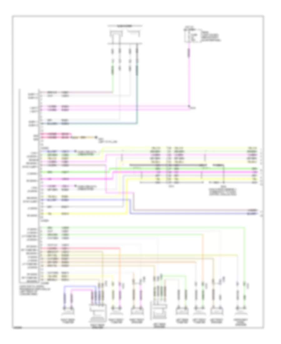
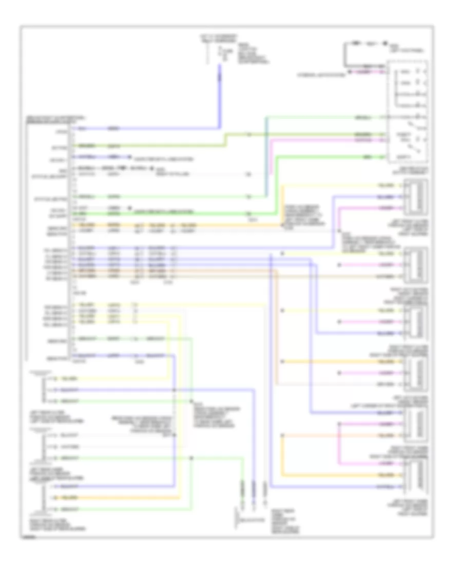
Navigation Wiring Diagram, with Sony (1 of 3) for Ford Escape S 2013
List of elements for Navigation Wiring Diagram, with Sony (1 of 3) for Ford Escape S 2013:
- Audio digital signal processing (dsp) module (left front of luggage area)
- C214
- C313
- C314
- C339
- C340
- C4326a
- C4326b
- C4326c
- Cme27
- Computer data lines system
- Enable
- Fuse 25a
- G401 (left "d" pillar)
- Gd180
- Gnd
- Hot at all times
- I can +
- I can -
- Instrument panel speaker
- Ip spkr +
- Ip spkr -
- Left front speaker
- Left front tweeter
- Left rear speaker
- Left rear tweeter
- Lf spkr +
- Lf spkr -
- Lf tweeter +
- Lf tweeter -
- Lr spkr +
- Lr spkr -
- Nca
- Rear junction box (behind right quarterpanel)
- Rf spkr +
- Rf spkr -
- Rf tweeter +
- Rf tweeter -
- Right front speaker
- Right front tweeter
- Right rear speaker
- Right rear tweeter
- Rme01
- Rme06
- Rme07
- Rme08
- Rme09
- Rme10
- Rme11
- Rme12
- Rme17
- Rme18
- Rme60
- Rme61
- Rme72
- Rme80
- Rr spkr +
- Rr spkr -
- S248 (main wiring assembly, in breakout to audio control module (acm))
- S418
- S419
- Sme23
- Subw 1+
- Subw 1-
- Subw 2+
- Subw 2-
- Subwoofer
- Sync alert+
- Sync alert-
- V batt
- Vdb13
- Vdb14
- Vme01
- Vme06
- Vme07
- Vme08
- Vme09
- Vme10
- Vme11
- Vme12
- Vme17
- Vme18
- Vme60
- Vme61
- Vme72
- Vme80
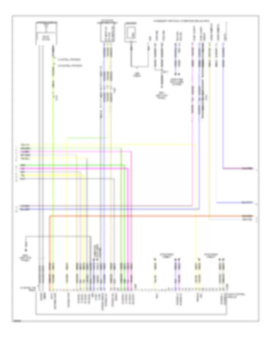
Navigation Wiring Diagram, with Sony (2 of 3) for Ford Escape S 2013
List of elements for Navigation Wiring Diagram, with Sony (2 of 3) for Ford Escape S 2013:
- (w/o sync) audio input jack
- Accessory protocol interface module (apim)
- Am/fm
- Antenna module
- Antenna pwr
- Audio control module
- Audio remote+
- Audio remote-
- Batt
- C214
- C240a
- C240b
- C327
- Cme27
- Cme44
- Coaxial cable
- Computer data lines system
- Data lines computer
- Dme17
- Dme37
- Dme80
- Enable
- G204 (left kick panel)
- Gd103
- Gd135
- Gnd
- Hs can +
- Hs can -
- I can +
- I can -
- Lf spkr +
- Lf spkr -
- Lr spkr +
- Lr spkr -
- Nca
- Pwr gnd
- Rf spkr +
- Rf spkr -
- Rme17
- Rme18
- Rme24
- Rme45
- Rme52
- Rme53
- Rme60
- Rme61
- Rme80
- Rr spkr +
- Rr spkr -
- S211
- Sbp06
- Sdars
- Sdl+
- Sdl-
- Shield
- Solid state
- St input 2l+
- St input 2r+
- St rtn
- Stereo 2l+
- Stereo 2r+
- Stereo l+
- Stereo l-
- Stereo r+
- Stereo r-
- Stereo rtn
- Stereo shield
- Sync alert+
- Sync alert-
- Sync radio circuit
- System
- Usb
- Usb cable
- Usb port
- Vbatt
- Vdb04
- Vdb05
- Vdb13
- Vdb14
- Vme14
- Vme17
- Vme18
- Vme37
- Vme38
- Vme52
- Vme53
- Vme58
- Vme59
- Vme60
- Vme61
- Vme80
- W/ satellite radio
- W/o satellite radio
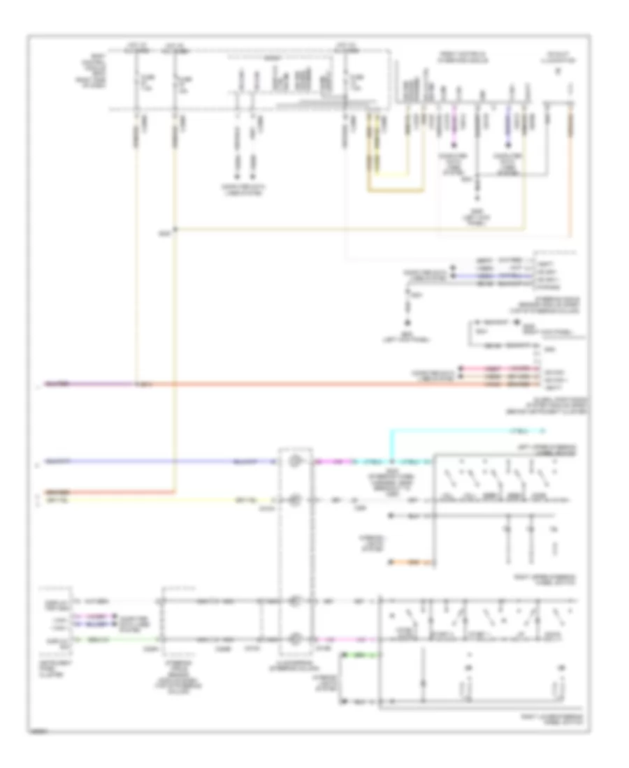
Navigation Wiring Diagram, with Sony (3 of 3) for Ford Escape S 2013
List of elements for Navigation Wiring Diagram, with Sony (3 of 3) for Ford Escape S 2013:
- Body control module (bcm) (right side of dash)
- C218a
- C218b
- C218c
- C226a
- C226b
- C2280c
- C2280e
- C2280f
- C260
- Ccd15
- Cd slot illumination
- Clockspring (steering column)
- Cls32
- Computer
- Computer data lines system
- Cpl87
- Ctrl sw ind
- Data lines system
- Display sig
- Display/ trip gnd
- Door lck
- Down
- Dr lck ctrl sw ind
- Front controls interface module
- Fuse 15a
- Fuse 7.5a
- G205 (left kick panel)
- G206 (right kick panel)
- Gd133
- Gd138
- Global positioning system module (gpsm) (behind instrument cluster)
- Gnd
- Hazard sig sw/
- Hot at all times
- Hs can +
- Hs can -
- I can +
- I can -
- Illum
- Instrument panel cluster
- Interior lights system
- Left upper steering wheel switch
- Micro
- Mode
- Ms can +
- Ms can -
- Nca
- Pwr gnd
- Right lower steering wheel switch
- Right upper steering wheel switch
- S214
- S221
- S235
- S241
- S242 (steering wheel harness, near breakout to c260)
- Sbp06
- Sbp07
- Seek+
- Seek-
- Sig sw/
- Start 1
- Start 2
- Steering angle sensor module (sasm) (top of steering column)
- Vbatt
- Vdb04
- Vdb05
- Vdb06
- Vdb07
- Vdb13
- Vdb14
- Vmn03
- Voice/ mute
- Vol+
- Vol-
- Warning
- Warning hazard
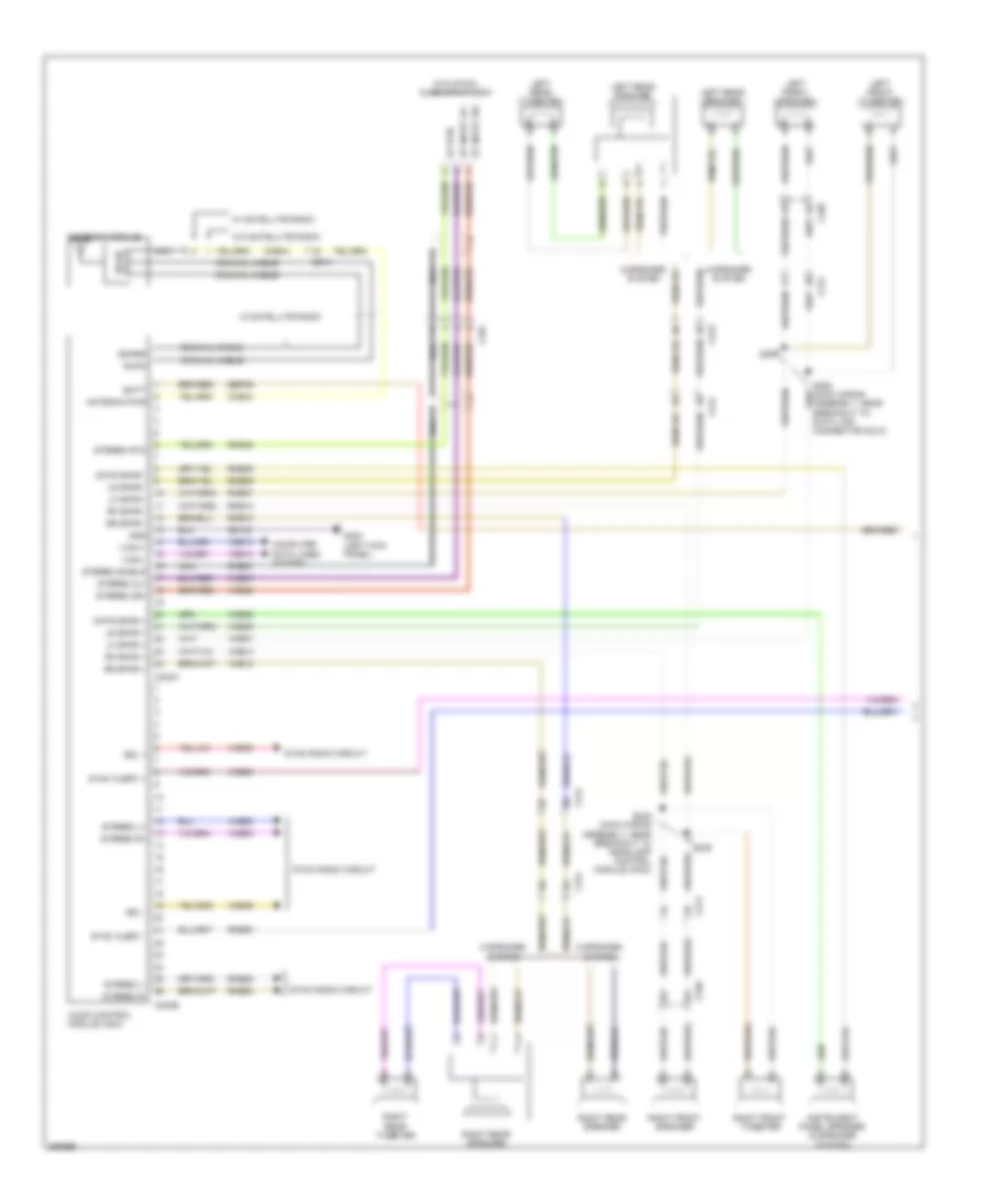
Navigation Wiring Diagram, without Sony (1 of 3) for Ford Escape S 2013
List of elements for Navigation Wiring Diagram, without Sony (1 of 3) for Ford Escape S 2013:
- (w/o sync) audio input jack
- 6 speaker system
- 9 speaker system
- Am/fm
- Antenna module
- Antenna pwr
- Audio control module (acm)
- Batt
- C214
- C240a
- C240b
- C313
- C314
- C327
- C339
- C340
- Cme44
- Cntr spkr +
- Cntr spkr -
- Coaxial cable
- Computer data lines system
- Dme37
- G204 (left kick panel)
- Gd103
- Gnd
- I can +
- I can -
- Instrument panel speaker (9 speaker system)
- Left front speaker
- Left front tweeter
- Left rear speaker
- Left rear tweeter
- Lf spkr +
- Lf spkr -
- Lr spkr +
- Lr spkr -
- Nca
- Rf spkr +
- Rf spkr -
- Right front speaker
- Right front tweeter
- Right rear speaker
- Right rear tweeter
- Rme06
- Rme07
- Rme09
- Rme10
- Rme12
- Rme45
- Rme52
- Rme53
- Rme80
- Rr spkr +
- Rr spkr -
- S207
- S208 (main wiring assembly, near breakout to data link connector (dlc))
- S239
- S240 (main wiring assembly, near breakout to headlamp control module (hcm))
- Sbp06
- Sdars
- Sdl +
- Sdl -
- St input 2l+
- St input 2r+
- St rtn
- State solid
- Stereo 2l+
- Stereo 2r+
- Stereo l+
- Stereo l-
- Stereo r+
- Stereo r-
- Stereo rtn
- Stereo shield
- Sync alert +
- Sync alert -
- Sync radio circuit
- Vdb13
- Vdb14
- Vme06
- Vme07
- Vme09
- Vme10
- Vme12
- Vme37
- Vme38
- Vme52
- Vme53
- Vme58
- Vme59
- Vme80
- W/ satellite radio
- W/o satellite radio
Navigation Wiring Diagram, without Sony (2 of 3) for Ford Escape S 2013
List of elements for Navigation Wiring Diagram, without Sony (2 of 3) for Ford Escape S 2013:
- Accessory protocol interface module (apim)
- Audio anti- theft sw
- Audio remote +
- Audio remote -
- Body control module (bcm) (right side of dash)
- C214
- C218a
- C218b
- C2280c
- C2280e
- C2280f
- C260
- Clockspring (steering column)
- Computer data lines system
- Dme80
- Front control/ display interface module (fcdim)
- Fuse 15a
- Fuse 7.5a
- G204 (left kick panel)
- Gd135
- Gd138
- Gnd
- Hot at all times
- Hs can +
- Hs can -
- Hs can+
- Hs can-
- I can+
- I can-
- Interior lights system
- Lin
- Micro
- Mode
- Nca
- Pwr gnd
- Right lower steering wheel switch
- Right upper steering wheel switch
- Rme24
- Rme80
- S211
- S214
- S217 (main wiring assembly, near breakout to in-vehicle temperature/ humidity sensor)
- S242 (steering wheel harness, near breakout to c260)
- Sbp06
- Seek+
- Seek-
- Shield
- Sync alert+
- Sync alert-
- Usb
- Usb cable
- Usb port
- Vbatt
- Vdb04
- Vdb05
- Vdb13
- Vdb14
- Vmc29
- Vme14
- Vme80
- Vmp19
- Voice/ mute
- Vol+
- Vol-
- W/ 4.2 inch display
- W/o 4.2 inch display
Navigation Wiring Diagram, without Sony (3 of 3) for Ford Escape S 2013
List of elements for Navigation Wiring Diagram, without Sony (3 of 3) for Ford Escape S 2013:
- (left kick panel) g205
- (or vdb13)
- C218b
- C218c
- C226a
- C226b
- C260
- Ccd15
- Cd slot illumination (w/ 8 inch display)
- Clockspring (steering column)
- Cls32
- Cmc29
- Computer data lines system
- Cpl87
- Display sig
- Display/ trip gnd
- Door locks system
- Down
- Front controls interface module
- G206 (right kick panel)
- Gd133
- Gd138
- Global positioning system module (gpsm) (behind instrument cluster)
- Gnd
- Hs can +
- Hs can -
- I can +
- I can + lin
- I can -
- I can-
- Illum
- Instrument panel cluster (ipc)
- Interior lights system
- Lck sw ind
- Left
- Left upper steering wheel switch
- Ms can +
- Ms can -
- Nca
- Pwr gnd
- Right
- Right upper steering wheel switch (w/ 4.2 inch display)
- Rmc27
- S221
- S241
- S242 (steering wheel harness, near breakout to c260)
- Sbp06
- Sbp07
- Sig sw
- Steering angle sensor module (sasm) (top of steering column)
- Vbatt
- Vdb04
- Vdb05
- Vdb06
- Vdb07
- Vdb14
- Vmc29
- Vmn03
- W/ 4.2 inch display
- W/ 8 inch display
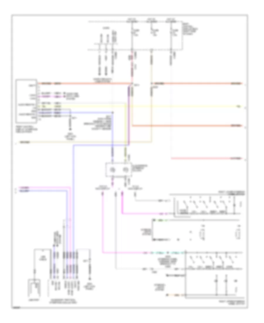
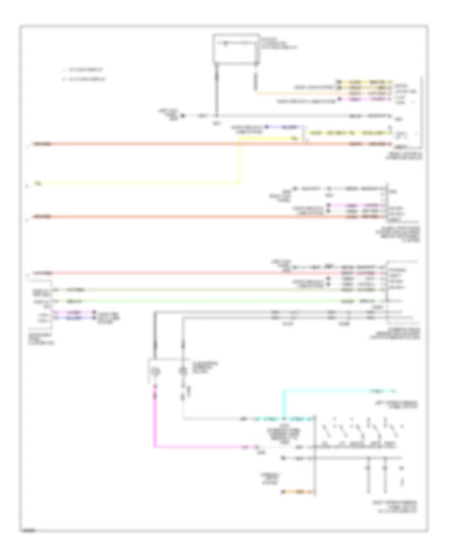
Parking Assistant Wiring Diagram for Ford Escape S 2013
List of elements for Parking Assistant Wiring Diagram for Ford Escape S 2013:
- (behind right quarterpanel) parking aid module (pam)
- (park aid sensor wiring assembly, near breakout to left front inner parking aid sensor) s158
- (rear park aid sensor wiring assembly, near breakout to rear inner left parking aid sensor) s417
- C134
- C210
- C214
- C4014a
- C4014b
- C4014c
- C432
- Cbr01
- Center stack switch assembly
- Cmp02
- Cmp18
- Cmp31
- Cmp32
- Computer data lines system
- Fil sens in
- Fir sens in
- Fol sens in
- For sens in
- Fuse 5a
- G205 (left kick panel)
- G400 (right "d" pillar)
- Gd152
- Gnd
- Hot w/ accessory relay energized
- Hs can +
- Hs can -
- Interior lights system
- Left active park assist sensor (left corner of front bumper fascia)
- Left front inner parking aid sensor (left side of front bumper)
- Left front outer parking aid sensor (left side of front bumper)
- Left rear inner parking aid sensor (left side of rear bumper)
- Left rear outer parking aid sensor (left side of rear bumper)
- Lf sens in
- Lmp06
- Lmp07
- Pass
- Rear junction box (rjb) (behind right quarterpanel)
- Rf sens in
- Right active park assist sensor (right corner of front bumper fascia)
- Right front inner parking aid sensor (right side of front bumper)
- Right front outer parking aid sensor (right side of front bumper)
- Right rear inner parking aid sensor (right side of rear bumper)
- Right rear outer parking aid sensor (right side of rear bumper)
- Ril sens in
- Rir sens in
- Rmp06
- Rmp07
- Rol sens in
- Ror sens in
- S157 (park aid sensor wiring assembly, near breakout to left front inner parking aid sensor)
- S221
- S400
- S416 (rear park aid sensor wiring assembly, near breakout to rear inner left parking aid sensor)
- Sapp
- Sens gnd
- Sens pwr
- Solid state
- Status led pas
- Status led sapp
- Sw pas
- Sw sapp
- Vdb04
- Vdb05
- Vmp10
- Vmp11
- Vmp12
- Vmp13
- Vmp14
- Vmp15
- Vmp16
- Vmp17
- Vmp21
- Vpm20
- Vpwr
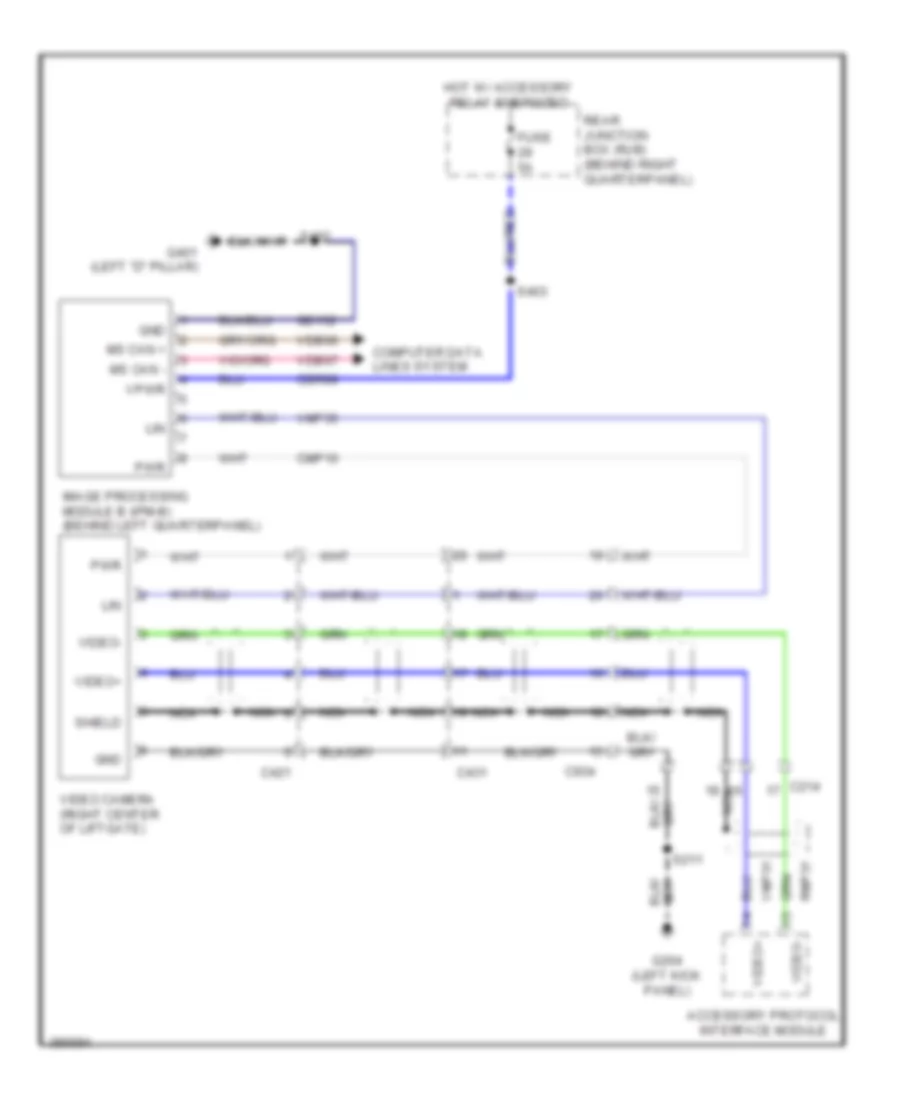
Rear Camera Wiring Diagram for Ford Escape S 2013
List of elements for Rear Camera Wiring Diagram for Ford Escape S 2013:
- Accessory protocol interface module
- C214
- C421
- C431
- C934
- Cbr99
- Cmp10
- Computer data lines system
- Fuse 5a
- G204 (left kick panel)
- G401 (left "d" pillar)
- Gd152
- Gnd
- Hot w/ accessory relay energized
- Image processing module b (ipm-b) (behind left quarterpanel)
- Lin
- Ms can +
- Ms can -
- Nca
- Pwr
- Rear junction box (rjb) (behind right quarterpanel)
- Rmp31
- S211
- S402
- S403
- Shield
- Vdb06
- Vdb07
- Video camera (right center of liftgate)
- Video+
- Video-
- Vmp31
- Vmp35
- Vpwr