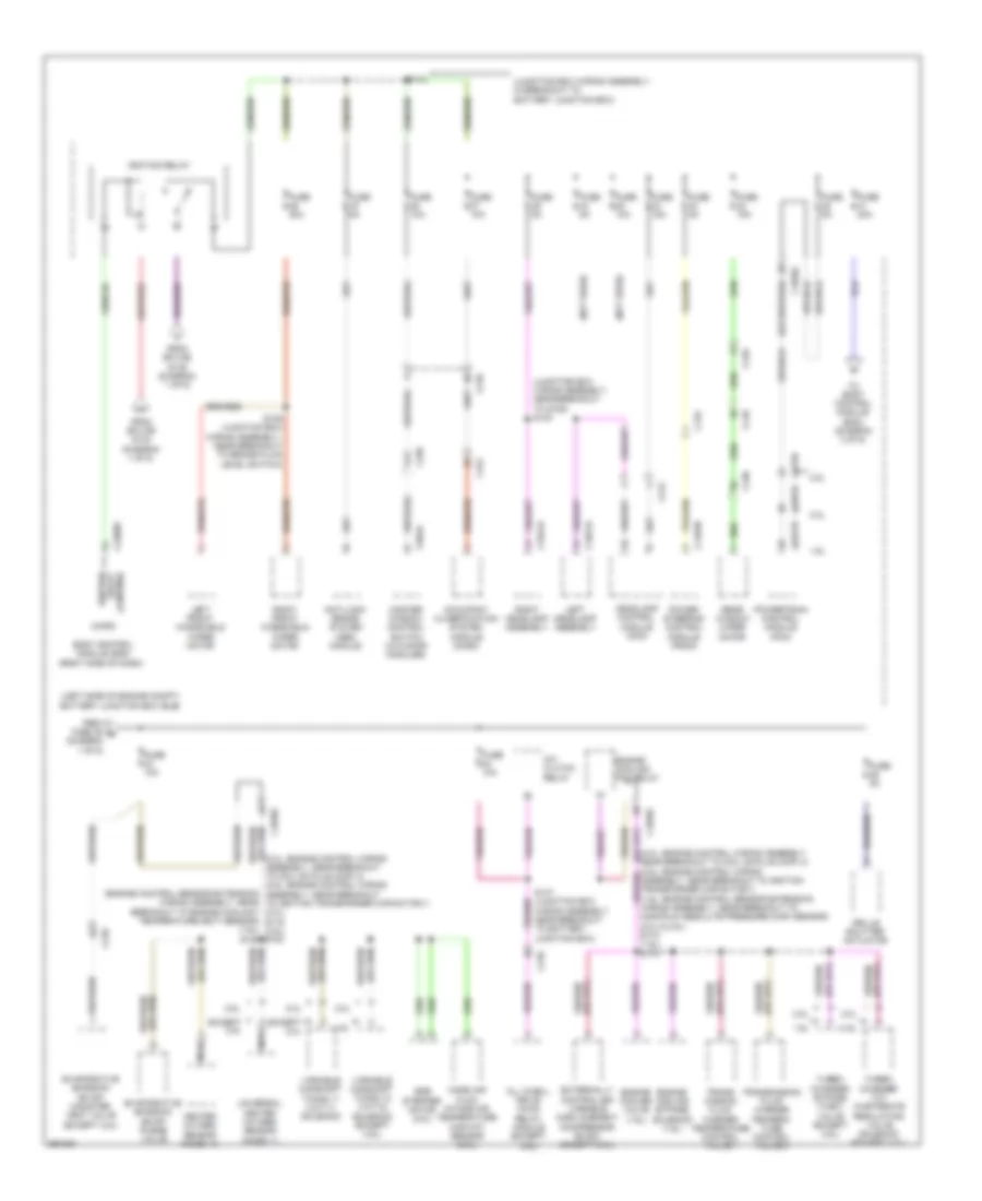
POWER DISTRIBUTION
Power Distribution Wiring Diagram (1 of 6) for Ford Escape S 2013

List of elements for Power Distribution Wiring Diagram (1 of 6) for Ford Escape S 2013:
- (2.0l: engine control wiring assembly, near breakout to coil on plug (cop) 2) (1.6l: engine control sensor extension wiring assembly, near breakout to coil on plug (cop) 2)
- (diagram 3 of 6)
- (diagram 4 of 6)
- (engine control wiring assembly, near breakout to (2.0l) s116 (1.6l) s122
- (junction box wiring assembly, in breakout to bjb) s144
- (left side of engine compt) battery junction box (bjb)
- (left side of engine compt) high current battery junction box (bjb)
- (right kick panel) g206
- 1.6l
- 2.0l
- 2.5l
- A/c clutch relay
- Anti-lock brake system (abs) module
- Battery
- Battery junction box (bjb) (left side of engine compt)
- Battery monitoring sensor
- Blower motor relay
- Body control module (bcm) (right side of dash)
- Brake pedal position (bpp) switch
- C1035a
- C1035b
- C1035c
- C1381b
- C1463a
- C1551b
- C1617a
- C1617b
- C1617c
- C1617d
- C1617e
- C1617f
- C1617g
- C1617h
- C1617j
- C1617l
- C175b
- C197a
- C210
- C211
- C212
- C219
- C2280g
- C2603a
- C327
- C339
- Coil on plug (cop) 1
- Coil on plug (cop) 2
- Coil on plug (cop) 3
- Coil on plug (cop) 4
- Console power point
- Electric booster heater
- Engine cooling fan relay
- Evaporative emission (evap) canister vent valve (2.5l)
- Except 2.0l
- Except 2.5l
- Front cigar lighter
- Fuel injector 3) (2.5l) s113
- Fuel pump relay
- Fuse 10a
- Fuse 15a
- Fuse 20a
- Fuse 30a
- Fuse 40a
- Fuse 5a
- G100 (left rear of engine compt)
- Generator
- Headlamp switch
- Horn relay
- Ignition transformer capacitor 1 (2.5l)
- Keypad switch assembly
- Liftgate/ decklid release relay
- Mega fuse 1 80a
- Mega fuse 2 150a
- Mega fuse 3 100a
- Mega fuse 4 50a
- Mega fuse 6 70a
- Mega fuse 60a
- Mega fuse 8 50a
- Mega fuse 80a
- Mega fuse 9 50a
- Micro
- Pcm power relay
- Power steering control module (pscm)
- Powertrain control module (pcm)
- Rear console power point
- Rear window defrost relay
- Red
- Red (battery cable wiring assembly, near breakout to generator) s155
- S131 (1.6l) s103 (2.0l) s112 (2.5l) (1.6l: engine control sensor extension wiring assembly, near breakout to c1019) (2.0l: engine control wiring assembly, in breakout to battery junction box (bjb)) (2.5l: engine control wiring assembly, in breakout to powertrain control module (pcm))
- S151 (power steering wiring assembly, near breakout to g108)
- S329
- Starter motor
- Starter relay
- To battery junction box (bjb) (diagram 2 of 6)
- To battery junction box (bjb) (diagram 6 of 6)
- To fuse 33 (diagram 2 of 6)
- To fuse 70
- To fuse 74
- To rear junction box (rjb) (diagram 5 of 6)
- To splice s401 (diagram 5 of 6)
- V batt
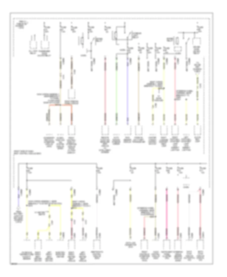
Power Distribution Wiring Diagram (2 of 6) for Ford Escape S 2013
List of elements for Power Distribution Wiring Diagram (2 of 6) for Ford Escape S 2013:
- (2.0l: engine control wiring assembly, near breakout to coil on plug (cop) 4) (2.5l: engine control wiring assembly, near breakout to ignition transformer capacitor 1) (2.0l) s119 (2.5l) s100
- (engine control sensor extension wiring assembly, near breakout to engine coolant temperature (ect) sensor) (1.6l) s128
- (junction box wiring assembly, in breakout to battery junction box)
- (junction box wiring assembly, near breakout to g105) s140
- (left side of engine compt) battery junction box (bjb)
- (not used)
- (right side of dash)
- 1.6l
- 2.0l
- 2.5l
- A/c clutch relay
- A13
- All whell drive (awd) relay module (except 2.5l)
- Anti-lock brake system (abs) module
- Body control module (bcm)
- C1021a
- C1035c
- C1041a
- C133
- C1381b
- C1463b
- C1551b
- C175b
- C210
- C212
- C2280d
- C312
- C339
- C410
- C438
- C504a
- Control relay ignition
- Egr stepper motor (2.5l)
- Engine cooler valve (1.6l)
- Engine cooling bypass solenoid (1.6l)
- Engine cooling fan relay
- Evaporative emission (evap) canister vent valve (except 2.5l)
- Evaporative emission (evap) purge valve
- Except 2.0l
- Except 2.5l
- Externally controlled variable displacement compressor (evdc) (except 2.5l)
- From fuse 35 g (diagram 1 of 6)
- From splice s144 (diagram 1 of 6)
- From splice s145 (diagram 1 of 6)
- Fuse 10a
- Fuse 15a
- Fuse 20a
- Fuse 50a
- Fuse 5a
- Grille shutter actuator
- Headlamp control module (hcm)
- Heated oxygen sensor (ho2s) 12
- Ignition relay
- Left front windshield wiper motor
- Left headlamp assembly
- Mass air flow intake air temperature (maf/iat) sensor (2.5l)
- Master window control switch (w/o door modules)
- Micro
- Nca
- Occupant classification system module (ocsm)
- Power steering control module (pscm)
- Powertrain control module (pcm)
- Rear window wiper motor
- Right front windshield wiper motor
- Right headlamp assembly
- S139 (junction box wiring assembly, near breakout to brake fluid level switch)
- S143
- S147 (junction box wiring assembly, near breakout to battery junction box)
- To body control module (bcm) (diagram 3 of 6)
- Trans- mission fluid warmer temperature control valve 1
- Transmission fluid warmer tempera- ture control valve 2
- Turbo- charger (tc) wastegate regulating valve solenoid (except 2.5l)
- Turbo- charger bypass (tcby) valve (except 2.5l)
- Universal heated oxygen sensor (ho2s) 11
- Variable camshaft timing 11 (vct11) solenoid
- Variable camshaft timing 12 (vct12) solenoid (except 2.5l)
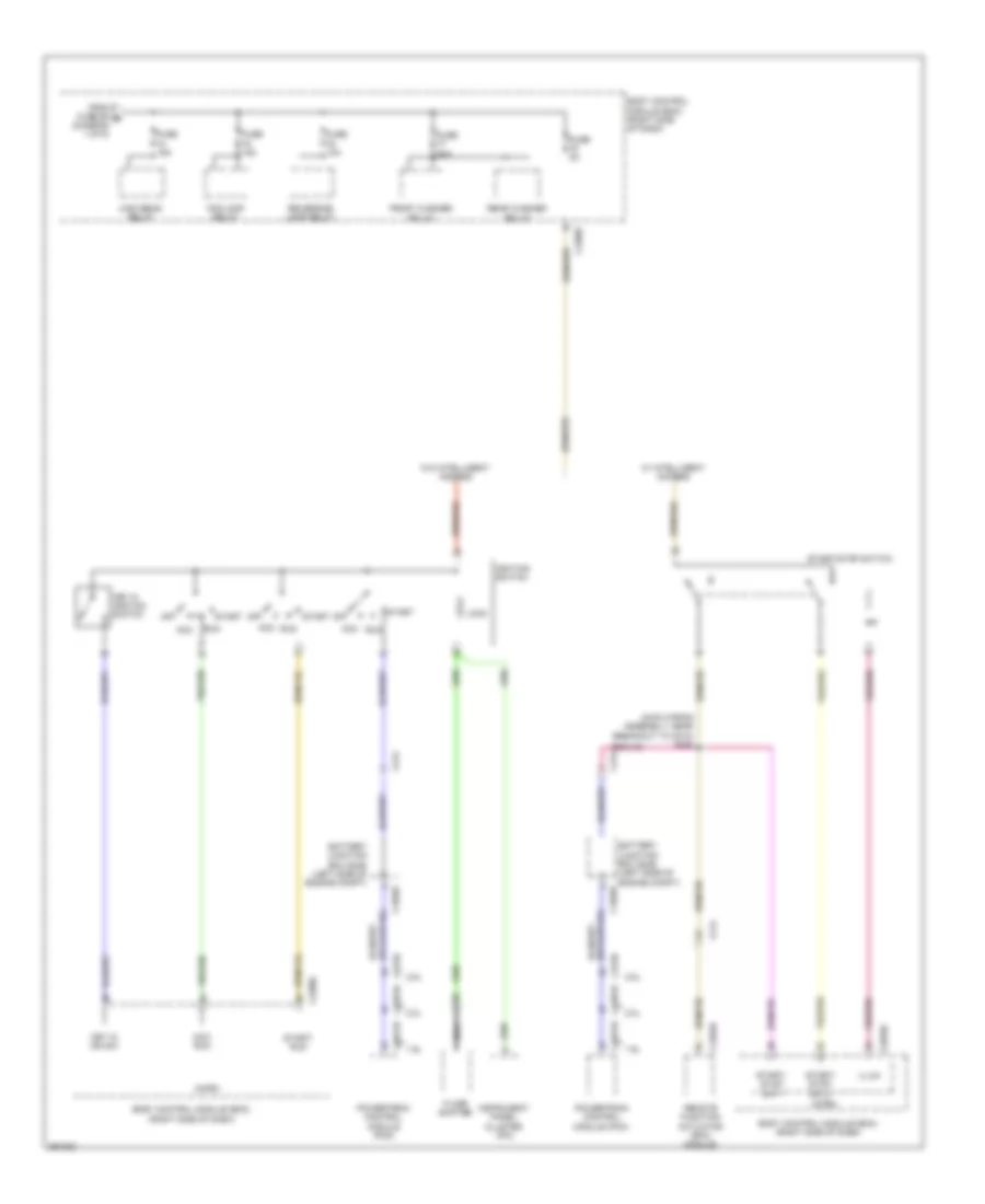
Power Distribution Wiring Diagram (3 of 6) for Ford Escape S 2013
List of elements for Power Distribution Wiring Diagram (3 of 6) for Ford Escape S 2013:
- (body wiring assembly, near breakout to c311) s314
- (body wiring assembly, near breakout to g200) s206
- (main wiring assembly, near breakout to panel/ floor mode door actuator) s214
- (main wiring assembly, near breakout to start/stop switch) s218
- (not used)
- (right side of dash) body control module (bcm)
- (steering wheel harness, near breakout to c260) s244
- (steering wheel harness, near breakout to clockspring) s235
- Accessory protocol interface module (apim)
- All lock relay
- Audio control module (acm)
- Auto- dimming interior mirror
- C214
- C215
- C226a
- C2280d
- C2280e
- C2280f
- C2280h
- C228b
- C2357a
- C240a
- C248
- C2603c
- C310a
- C311
- C312
- C327
- C329a
- C339
- C359a
- Data link connector (dlc)
- Datc hvac module (automatic a/c)
- Driver door unlock relay
- Electric booster heater
- Emtc hvac module (manual a/c)
- From battery junction box (bjb) (diagram 2 of 6)
- From fuse 65 c (diagram 1 of 6)
- Front control/ display interface module (fcdim) (4.2 inch display)
- Front controls interface module (fcim)
- Fuse 10a
- Fuse 15a
- Fuse 20a
- Fuse 5a
- Fuse 7.5a
- Global position- ing system module (gpsm)
- Glove box lamp
- In-vehicle temperature/ humidity sensor
- Instrument panel cluster (ipc)
- Interior light relay
- Left footwell courtesy lamp (w/o ambient lighting)
- Left front heated seat module
- Left front seat heater switch
- Master window control switch
- Micro
- Passenger door unlock relay
- Passive anti-theft transceiver
- Rain sensor module
- Remote function receiver (rfr) module (w/ intelligent access)
- Restraints control module (rcm)
- Right footwell courtesy lamp (w/o ambient lighting)
- Right front heated seat module
- Right front seat heater switch
- Right luggage compart- ment lamp
- Roof opening panel module
- Spare relay
- Steering angle sensor module (sasm)
- To splice s901 (diagram 6 of 6)
- W/ door modules
- W/ heated seats
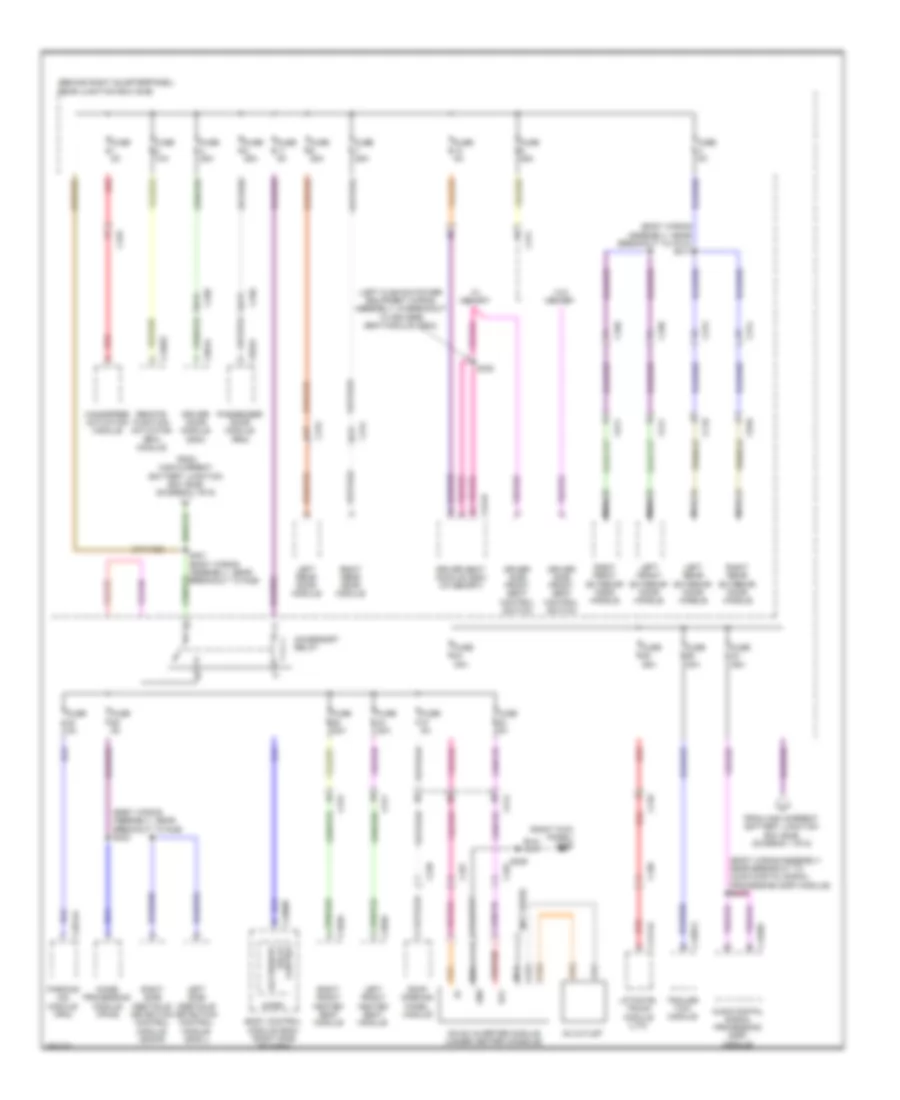
Power Distribution Wiring Diagram (4 of 6) for Ford Escape S 2013
List of elements for Power Distribution Wiring Diagram (4 of 6) for Ford Escape S 2013:
- (main wiring assembly, near breakout to c212) s246
- 1.6l
- 2.0l
- 2.5l
- Acc
- Acc run
- Acc/ run
- Battery junction box (bjb) (left side of engine compt)
- Body control module (bcm) (right side of dash)
- C1035c
- C1381b
- C1551b
- C175b
- C212
- C214
- C2280c
- C2280f
- C4392d
- Floor shifter
- Fog lamp relay
- From fuse 56 b (diagram 1 of 6)
- Front washer relay
- Fuse 10a
- Fuse 15a
- Fuse 20a
- Fuse 5a
- High beam relay
- Ignition switch
- Illum
- Instrument panel cluster (ipc)
- Key in ign sw
- Key in ignition switch
- Lock
- Micro
- Nca
- Off
- Powertrain control module (pcm)
- Rear washer relay
- Remote function actuator (rfa) module
- Reversing lamp relay
- Run
- Start
- Start/ run
- Start/ stop sw 1
- Start/ stop sw 2
- Start/stop switch
- W/ intelligent access
- W/o intelligent access
Power Distribution Wiring Diagram (5 of 6) for Ford Escape S 2013
List of elements for Power Distribution Wiring Diagram (5 of 6) for Ford Escape S 2013:
- (behind right quarterpanel) rear junction box (rjb)
- (body wiring assembly, near breakout to audio digital signal processing (dsp) module) s419
- (body wiring assembly, near breakout to c312) s311
- (body wiring assembly, near breakout to rjb) s403
- (left cushion power equipment wiring assembly, in breakout to driver's seat module (dsm))
- (not used)
- (right kick panel) g206
- A14
- A17
- Ac outlet
- Acc
- Accessory relay
- Audio digital signal processing (dsp) module
- Body control module (bcm) (right side of dash)
- C214
- C2280b
- C248
- C311
- C312
- C313
- C314
- C327
- C329a
- C339
- C340
- C341d
- C359a
- C4014a
- C410
- C4174a
- C432
- C4326c
- C438
- C4392c
- C4397a
- C501a
- C511
- C611
- C652a
- C710
- C810
- Control relay accessory
- Dc/ac inverter module (under center console)
- Driver door module (ddm)
- Driver seat module (dsm) (w/ memory)
- Driver side front seat control switch
- From high current battery junction box (bjb) (diagram 1 of 6)
- Fuse 10a
- Fuse 20a
- Fuse 25a
- Fuse 30a
- Fuse 40a
- Fuse 5a
- Gnd
- Handsfree actuation module
- Image processing module (ipm-b)
- Left front exterior door handle
- Left front heated seat module
- Left rear door module
- Left rear exterior door handle
- Left side obstacle detection control module (sod-l)
- Liftgate/ trunk module (ltm)
- Micro
- Nca
- Parking aid module (pam)
- Passenger door module (pdm)
- Red
- Remote function actuator (rfa) module
- Right front exterior door handle
- Right front heated seat module
- Right rear door module
- Right rear exterior door handle
- Right side obstacle detection control module (sod-r)
- Roof opening panel module
- S329
- S330
- S401 (body wiring assembly, near breakout to rjb)
- Trailer tow module
- W/ memory
- W/o memory
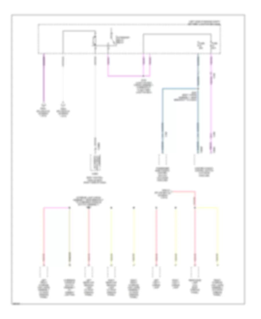
Power Distribution Wiring Diagram (6 of 6) for Ford Escape S 2013
List of elements for Power Distribution Wiring Diagram (6 of 6) for Ford Escape S 2013:
- (interior lamp wiring assembly, near breakout to overhead console switch assembly) s901
- (left side of engine compt) battery junction box (bjb)
- A11
- A14
- Accessory delay relay
- Body control module (bcm) (right side of dash)
- C210
- C2280a
- C339
- C340
- C504b
- C504c
- Control delay relay accessory
- From splice s144 (diagram 1 of 6)
- From splice s145 (diagram 1 of 6)
- From splice s244 j (diagram 3 of 6)
- Front interior/ map lamps assembly (w/o roof opening panel)
- Fuse 25a
- Left front interior/ map lamps assembly (w/ roof opening panel)
- Left rear map reading lamp (w/ roof opening panel)
- Left vanity mirror lamp
- Master window control switch (w/o door modules)
- Micro
- Overhead console switch assembly (w/ ambient lighting)
- Passenger side window control switch (w/o door modules)
- Rear dome lamp (w/o roof opening panel)
- Right front interior/ map lamps assembly (w/ roof opening panel)
- Right rear map reading lamp (w/ roof opening panel)
- Right vanity mirror lamp
- S182 (junction box wiring assembly, in breakout to battery junction box)
- S300 (body wiring assembly, near breakout to c340a)