ANTI-LOCK BRAKES
Anti-lock Brakes Wiring Diagram for Ford Explorer Sport Trac 2004
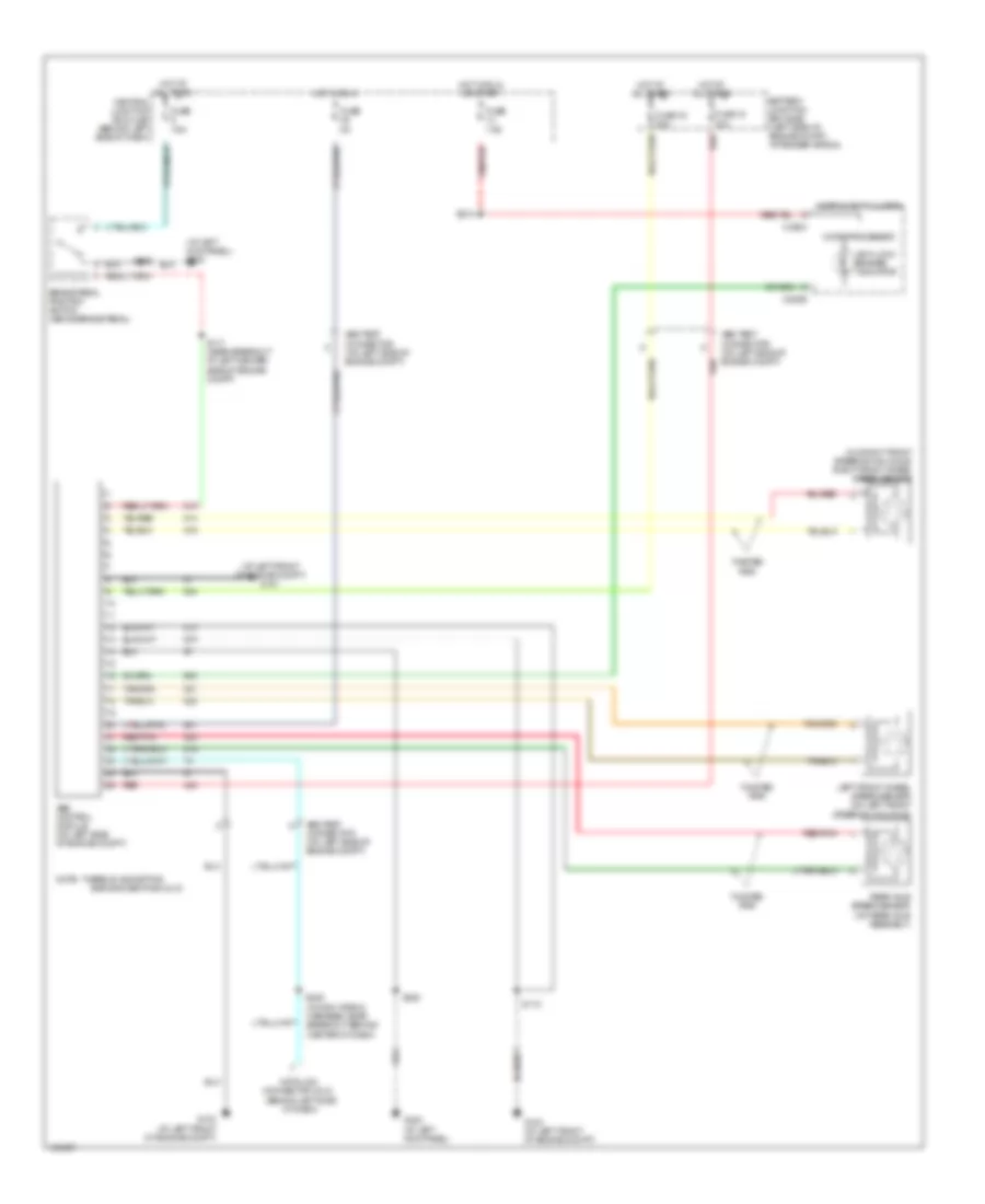
List of elements for Anti-lock Brakes Wiring Diagram for Ford Explorer Sport Trac 2004:
- (at left front of engine compt) g101
- (at left kick panel) g300
- (behind left side of dash)
- (on right front steering knuckle) right front wheel speed sensor
- Abs control module (on left side of engine compt)
- Abs test connector (on left side of engine compt)
- Anti-lock brakes indicator
- Bar across pins 8 & 16
- Battery junction box (bjb) (left side of engine compt, at fender apron)
- Brake pedal position switch (above brake pedal)
- C220a
- C220b
- Central junction box (cjb) (behind left side of dash)
- Data link connector (dlc)
- Fuse 16 50a
- Fuse 18 30a
- Fuse 5a
- Fuse 7.5a
- G102 (at left front of engine compt)
- G103 (at left front of engine compt)
- G300 (at left kick panel)
- Hot at all times
- Hot in run
- Hot in run or start
- Instrument cluster
- Left front wheel speed sensor (on left front steering knuckle)
- Microprocessor
- Note: there is a shorting
- Rear axle speed sensor (on rear axle assembly)
- Red
- Red/pnk
- S117 (near breakout at left center side of engine compt)
- S118
- S208 (in main wiring harness, near breakout behind center of dash)
- S218
- S320
- Twisted pair
 English