POWER DISTRIBUTION
Power Distribution Wiring Diagram (1 of 2) for Ford Explorer Sport Trac 2004

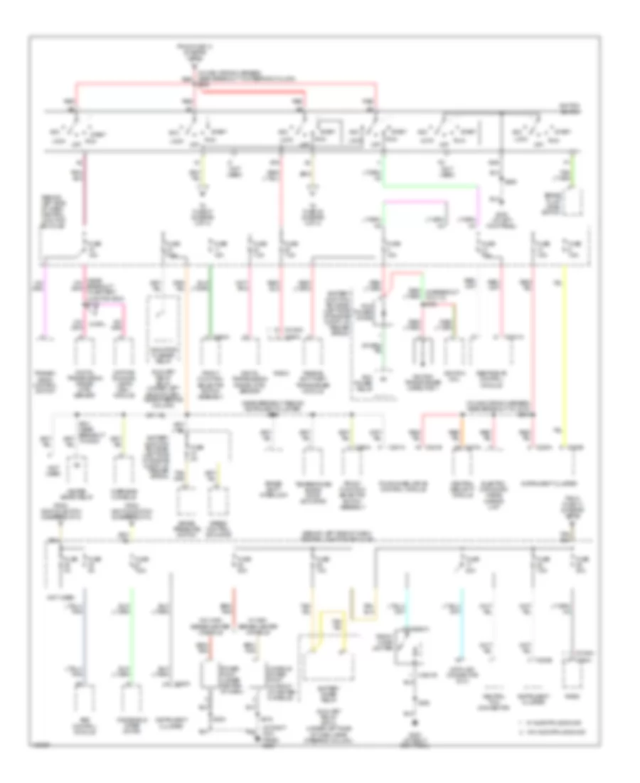
List of elements for Power Distribution Wiring Diagram (1 of 2) for Ford Explorer Sport Trac 2004:
- (in battery cable assembly, red near breakout at left center side of engine compt) s130
- (in body main wiring harness, near breakout to g300) s333
- (in dash panel to headlamp junction wiring harness, near breakout to battery junction box) s147
- (in main wiring harness, near breakout behind center of dash) s250
- (in main wiring harness, near breakout behind driver side of dash) s226
- (in main wiring harness, near breakout in steering wheel) s211
- (in seat control feed jumper wiring harness, near breakout to c315) s335
- (in seat control feed jumper wiring harness, near breakout under driver seat) s338
- (left side of engine compartment, at fender apron) battery junction box (bjb)
- (near breakout to battery junction box) s114
- A/c clutch relay
- Abs control module
- Autolamp headlamp relay
- Auxiliary relay box 2 (under left side of dash, near steering column)
- Battery
- Battery junction box (bjb) (left side of engine compt, at fender apron)
- Blower motor relay
- Brake pedal position switch
- C202b
- C205a
- C274a
- C274b
- C281a
- C3041a
- C466a
- Central junction box (cjb) (behind left side of dash)
- Central security module
- Daytime running lamps (drl) module
- Door lock relay
- Door unlock relay
- Driver side front seat adjust switch
- Exterior rear view mirror switch
- Fog lamp relay
- Four-wheel drive control module
- From fuse 15 (diagram 1 of 2)
- From fuse 34 (diagram 1 of 2)
- Fuel pump relay
- Fuse 10a
- Fuse 15a
- Fuse 20a
- Fuse 25a
- Fuse 30a
- Fuse 40a
- Fuse 47a 20a
- Fuse 47b 20a
- Fuse 50a
- Fuse 5a
- Fuse 7.5a
- G300 (at left kick panel)
- Generator
- Harness, near breakout in steering wheel) s212
- Heated seats relay
- Horn relay
- Indicator flasher relay
- Left front lumbar adjust switch
- Main light switch
- Multi- function switch
- Nca
- Passenger side front seat adjust switch
- Pcm power relay
- Pnk
- Powertrain control module (pcm)
- Rear power point (rear of vehicle, on left side)
- Rear window motor
- Red
- Right front lumbar adjust switch
- Roof opening panel module
- S131 (in battery cable assembly, near breakout at left center side of engine compt)
- S405
- Starter motor
- Starter relay
- Subwoofer amplifier
- To fuse (diagram 1 of 2)
- To fuse 14 (diagram 1 of 2)
- To fuse 25 (diagram 2 of 2)
- To s228 (diagram 2 of 2)
- Trailer tow relay
- W/ autolamps
- Window safety relay
- Windshield wiper relay
- Xls
- Xlt
Power Distribution Wiring Diagram (2 of 2) for Ford Explorer Sport Trac 2004
List of elements for Power Distribution Wiring Diagram (2 of 2) for Ford Explorer Sport Trac 2004:
- (at right kick panel) g200
- (behind left side of dash) central junction box (cjb)
- (in main wiring harness, near breakout to c215) s218
- (in main wiring harness, near breakout to steering column) red
- (near breakout behind instrument cluster) s216
- (not used)
- Abs control module
- Acc
- Auxiliary relay box 2 (under left side of dash, near steering column)
- Battery junction box (bjb) (left side of engine compt, at fender apron)
- Battery saver relay
- Brake fluid level switch
- Brake pressure switch
- Brake shift interlock
- C2031a
- C2031b
- C2041a
- C2188a
- C220a
- C220b
- C274a
- C281a
- C281b
- C290a
- C294a
- Central security module
- Console power point (in front of center console)
- Data link connector (dlc)
- Daytime running lamps (drl) module
- Digital transmission range (dtr) sensor
- Electro- chromatic inside mirror unit
- Four-wheel drive control module
- From fuse 13 (diagram 1 of 2)
- From fuse 14 (diagram 1 of 2)
- From ignition switch (diagram 2 of 2)
- Front cigar lighter
- Front function selector switch assembly
- Fuse 0a
- Fuse 10a
- Fuse 15a
- Fuse 20a
- Fuse 2a
- Fuse 5a
- Fuse 7.5a
- G200 (at right kick panel)
- G300 (at left kick panel)
- Gnd
- Heated seats relay
- Ignition coil
- Ignition switch
- Ignition transformer capacitor 1
- Indicator flasher relay
- Instrument cluster
- Lock
- Neutral tow connector
- Off
- Overhead console
- Passive anti-theft transceiver module
- Pcm power diode
- Pcm power relay
- Power point (under center of dash)
- Radio
- Red
- Restraints control module
- Run
- S203
- S206
- S228
- S316
- Speed control actuator
- Sta
- Start
- Temperature blend door actuator
- To fuse 27 (diagram 2 of 2)
- To fuse 35 (diagram 2 of 2)
- Transmi- ssion control switch
- W/ audiophile sound
- W/ drl
- W/ high series center console
- W/o audiophile sound
- W/o high series center console
- Windshield wiper motor