CRUISE CONTROL
Cruise Control Wiring Diagram for Ford Explorer Sport Trac 2004
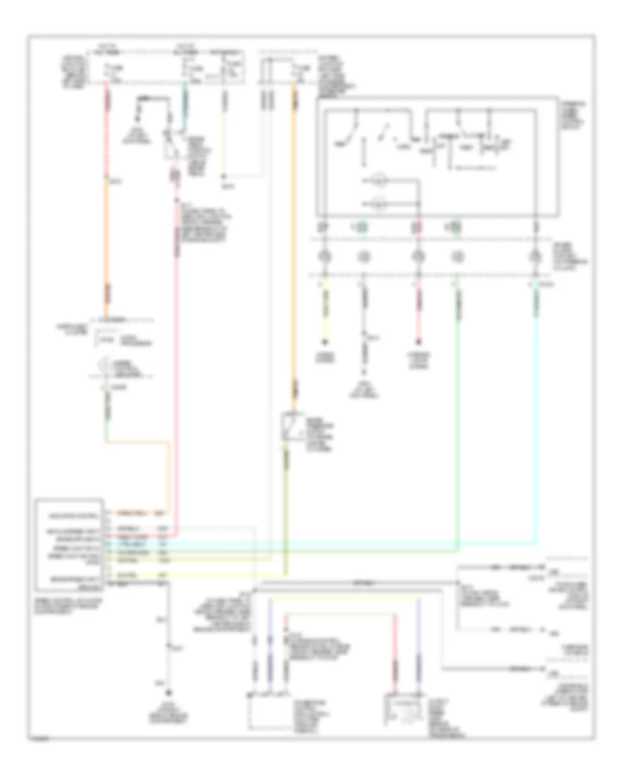
List of elements for Cruise Control Wiring Diagram for Ford Explorer Sport Trac 2004:
- Air bag sliding contact (on steering column)
- Battery junction box (bjb) (left side of engine compartment, at fender apron)
- Brake pedal position switch (above brake pedal)
- Brake press input
- Brake pressure switch (on brake master cylinder)
- C218a
- C220a
- C220b
- C281b
- Central junction box (cjb) (behind left side of dash)
- Coast
- Four-wheel drive control module (at right kick panel)
- Fuse 2a
- Fuse 7.5a
- G105 (at right side of engine compartment)
- G204 (at left kick panel)
- G300 (at left kick panel)
- Ground
- Horn
- Horns system
- Hot at all times
- Hot in run
- Indicator control
- Instrument cluster
- Interior lights system
- Micro- processor
- Off
- Output shaft speed (oss) sensor (on rear of transmission)
- Overhead console
- Powertrain control module (pcm) (mounted through firewall)
- Red/
- Rest
- Resume
- S116 (in dash panel to headlamp junction wiring harness, near breakout at left center side of engine compartment)
- S117 (in dash panel to headlamp junction wiring harness, near breakout at left center side of engine compt)
- S127
- S143 (in engine control sensor & fuel charge wiring harness, near breakout to g100)
- S206
- S213 (in main wiring harness, near breakout to c215)
- S214
- S216
- S218
- Set/ acc
- Speed cont sw gnd
- Speed cont sw in
- Speed control actuator (in right rear of engine compartment)
- Speed control indicator
- Steering wheel/ speed control switch
- Vehicle speed input
- Vpwr
- Vss
- Windshield wiper motor (left of center, at rear of engine compt)
 English