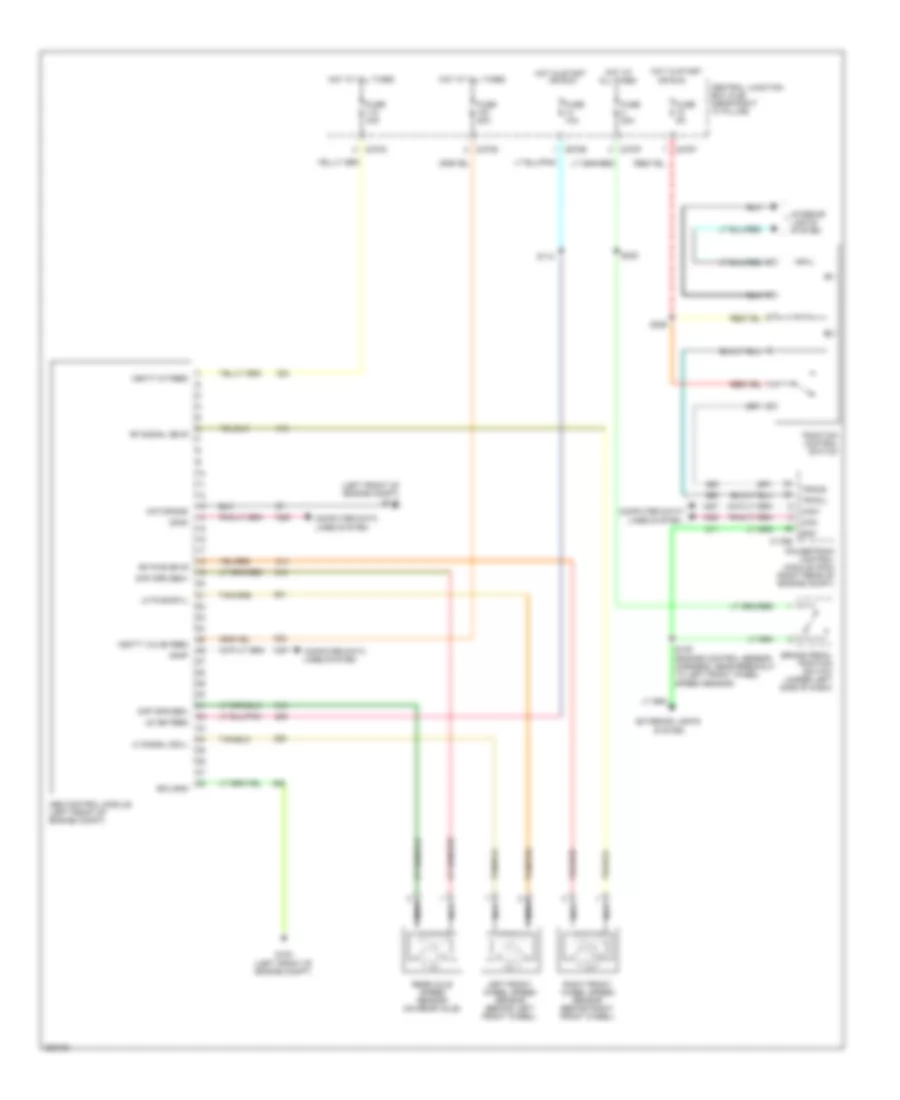
ANTI-LOCK BRAKES
Anti-lock Brakes Wiring Diagram for Ford Pickup F150 2008
List of elements for Anti-lock Brakes Wiring Diagram for Ford Pickup F150 2008:
- (left front of engine compt) g110
- Abs control module (left front of engine compt)
- Boo
- Brake pedal position switch (under left side of dash)
- C175b
- C270b
- C270c
- C270d
- C270f
- Can+
- Can-
- Canm
- Canp
- Central junction box (cjb) (near right "a" pillar)
- Computer data
- Computer data lines system
- Diff spd sen+
- Diff spd sen-
- Ecu gnd
- Exterior lights
- Fuse 10a
- Fuse 20a
- Fuse 40a
- Fuse 5a
- G108 (left front of engine compt)
- Hot at all times
- Hot in start
- Hot in start or run
- Interior lights system
- Left front wheel speed sensor (behind left front wheel)
- Lf pwr dpvl
- Lf signal dsvl
- Lines system
- Motor gnd
- Nca
- Or run
- Powertrain control module (pcm) (right rear of engine compt)
- Rear axle speed sensor (on rear axle)
- Rf pwr dpvr
- Rf signal dsvr
- Right front wheel speed sensor (behind right front wheel)
- S109 (engine control sensor harness, near breakout to left front wheel speed sensor)
- S112
- S220
- S225
- System
- Tracil
- Tracs
- Traction control switch
- Uz ign feed
- Vbatt mt feed
- Vbatt valve feed
 English