ENGINE PERFORMANCE
4.2L
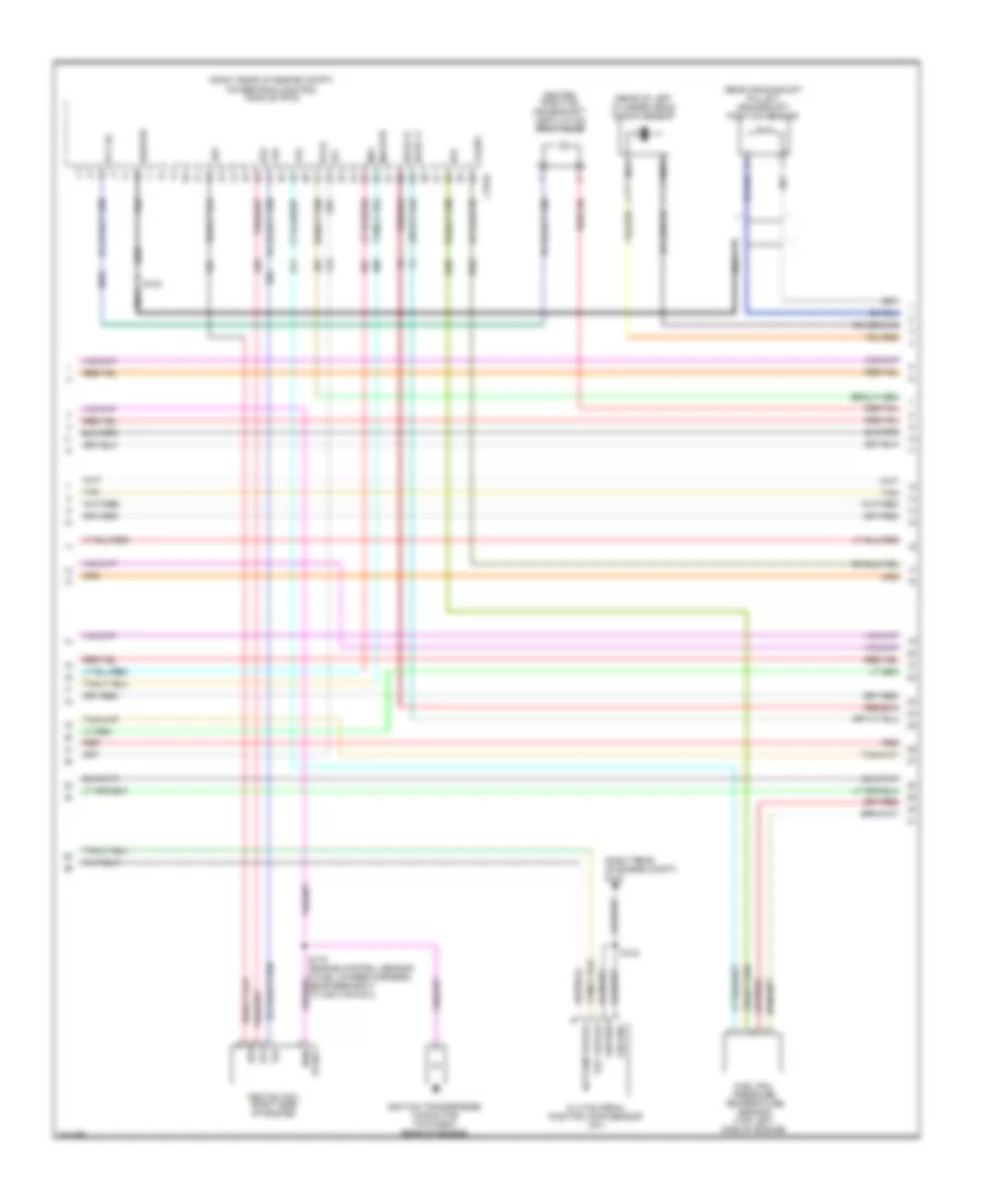
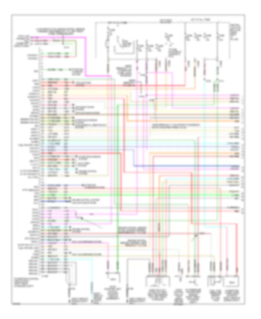
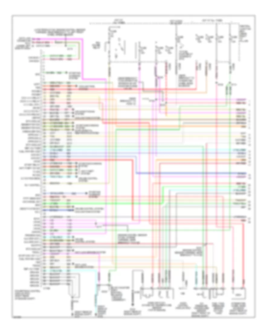
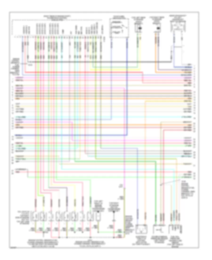
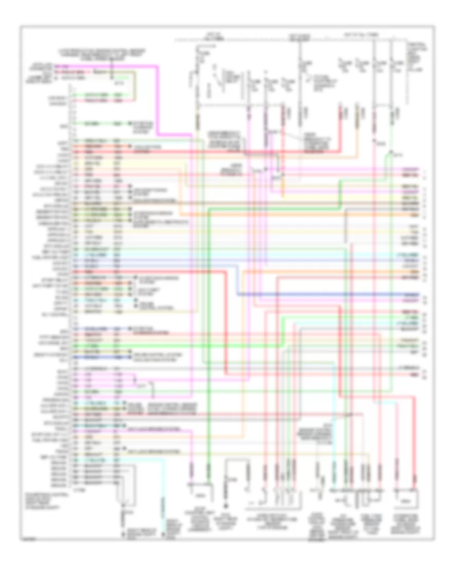
4.2L, Engine Performance Wiring Diagram (1 of 6) for Ford Pickup F150 2008

List of elements for 4.2L, Engine Performance Wiring Diagram (1 of 6) for Ford Pickup F150 2008:
- (engine control sensor harness, near breakout to c139)
- (late production: engine control sensor harness, near breakout to left front wheel speed sensor)
- (near breakout to c139)
- (near breakout to evaporative emission (evap) canister purge valve)
- (near breakout to ho2s 12)
- (near breakout to integrated wheel ends solenoid)
- (right rear of engine compt) g102
- (right rear of engine compt) g103
- A/c pressure transducer sensor (right front of engine compt)
- Accr
- Accs
- Acpt
- Air conditioning system
- Anti-lock brake system
- Anti-theft system
- App1
- App2
- App3
- Audio control module (acm) (behind center of dash)
- Boo
- Bps
- Bvref
- C175b
- C290a
- Can h
- Can l
- Canvnt
- Case gnd
- Central junction box (near right "a" pillar)
- Connector (dlc) (under left side of dash)
- Cooling fans system
- Cpp bt
- Cpp tt
- Cruise control system
- Data link
- Etc ref
- Etcref
- Etcrtn
- Evap canister vent control solenoid (vehicle underbody)
- Evm
- Fcv
- Feps
- Fpc
- Fpm
- Fss
- Ftpt
- Fuel tank pressure sensor (at fuel tank)
- Fuse 15a
- Fuse 5a
- Fuse 7.5a
- G103 (right rear of engine compt)
- Gen com
- Gen mon
- Hot at all times
- Ign sw
- Kapwr
- Led out
- Mass air flow/ intake air temperature sensor (left side of engine)
- Pcm power relay
- Pcm pwr rly out
- Powertrain control module (pcm) (right rear of engine compt)
- Pwr gnd
- Rdi
- Red
- Red/pnk
- Rx in
- S102
- S104
- S106
- S107
- S113
- S117
- S118
- S140
- S172
- S177
- Sccs
- Sccsrtn
- Sig rtn
- Smc
- Starting/ charging system
- Starting/charging system
- Tan
- Tcs
- To fuel pump relay (diagram 5 of 6)
- Tracil
- Tracs
- Tx out
- Vbpwr
- Vpwr
- Vsout
- Vss
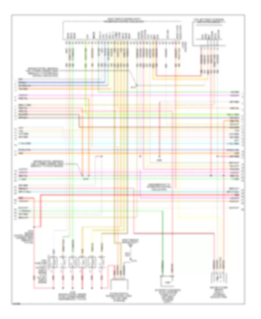
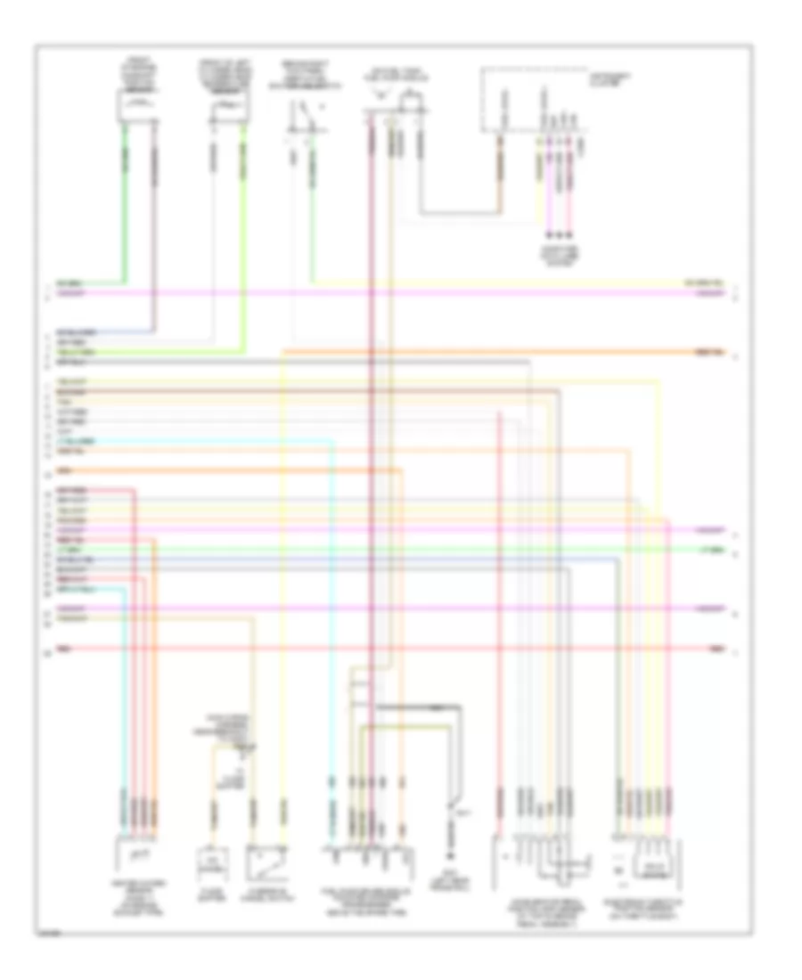
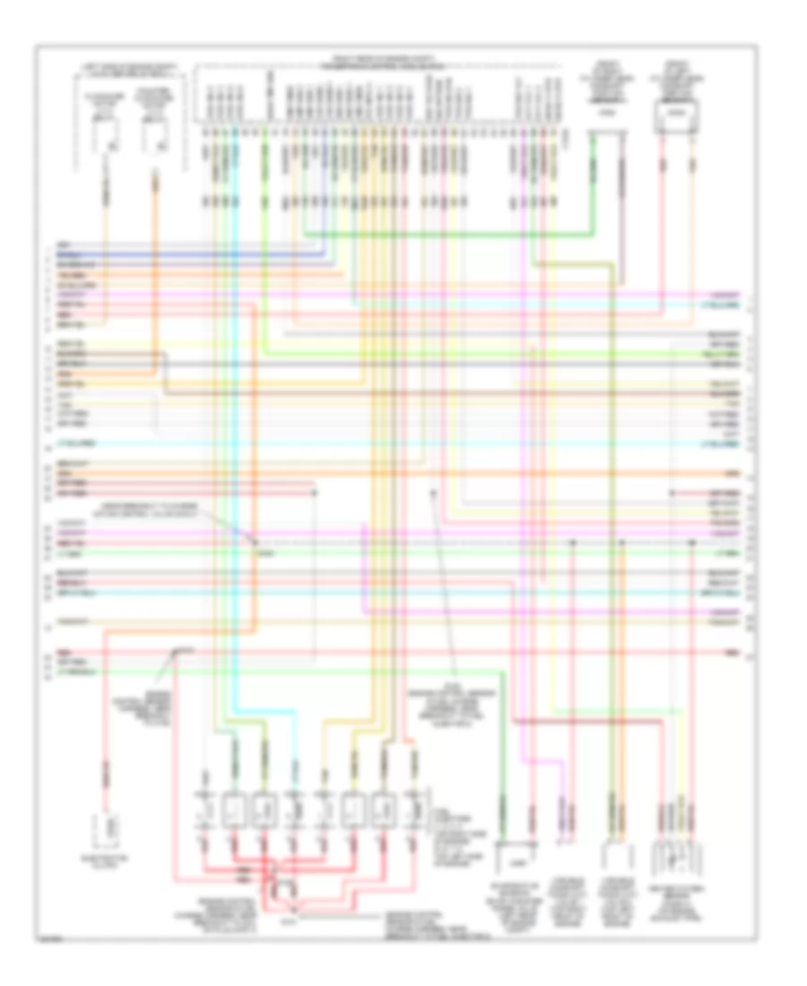
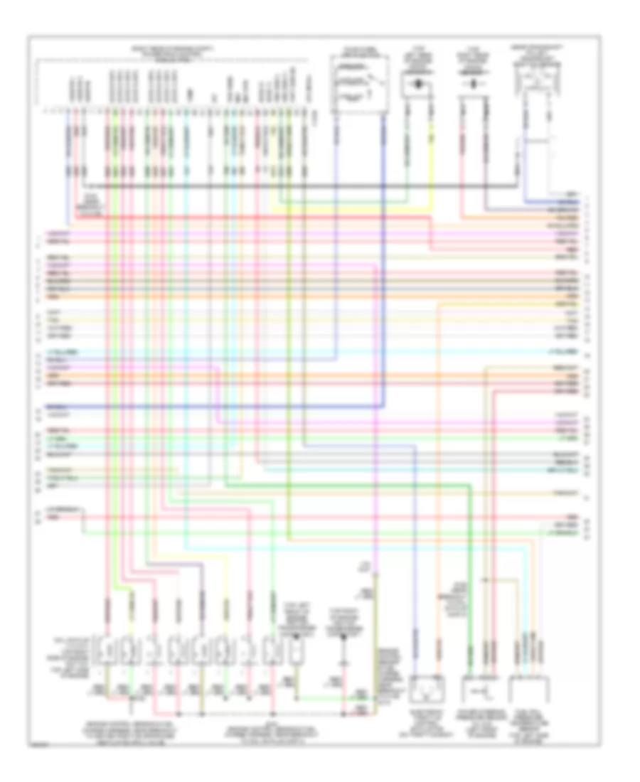
4.2L, Engine Performance Wiring Diagram (2 of 6) for Ford Pickup F150 2008
List of elements for 4.2L, Engine Performance Wiring Diagram (2 of 6) for Ford Pickup F150 2008:
- (near crankshaft pulley) crankshaft position sensor
- (rear of left cylinder head) knock sensor
- (right rear of engine compt) g103
- (right rear of engine compt) powertrain control module (pcm)
- 1a5
- 2c6
- 4b3
- Bottom travel
- C175e
- Clutch pedal position (cpp) sensor (m/t)
- Dpfe
- Frt
- Fuel rail pressure temperature sensor (top left side of engine)
- Ground
- Heated positive crankshaft ventilation (pcv) valve
- Ho2s 11
- Ho2s 21
- Iat
- Ignition coil (right side of engine)
- Ignition transformer capacitor (top right rear of engine)
- Ips
- Maf
- Mafrtn
- Nca
- Pcv hc
- Red
- Run/ start
- S102
- S123
- Shdrtn
- Tacm +
- Tan
- Top travel
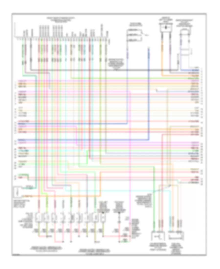
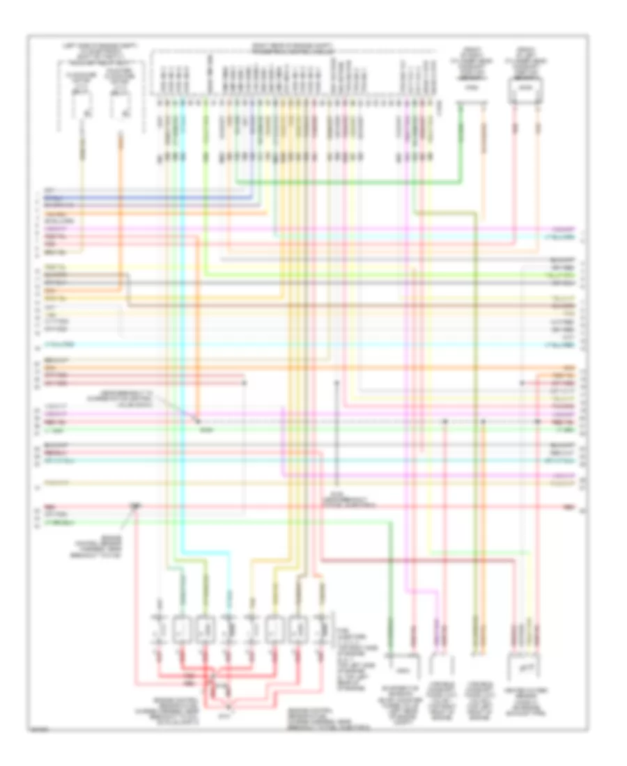
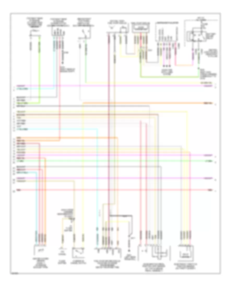
4.2L, Engine Performance Wiring Diagram (3 of 6) for Ford Pickup F150 2008
List of elements for 4.2L, Engine Performance Wiring Diagram (3 of 6) for Ford Pickup F150 2008:
- (engine control sensor & fuel charge harness, near breakout to knock sensor)
- (engine control sensor & fuel charge harness, near breakout to powertrain control module (pcm))
- (near breakout to powertrain control module (pcm))
- (partial)
- (right rear of engine compt) g103
- (right rear of engine compt) powertrain control module (pcm)
- (top left front of engine) egr system module
- Bref
- Bvref
- C175e
- Cht
- Cid 1 v
- Ckp +
- Ckp -
- Dpfe
- E imrc
- Etc ref
- Etcrtn
- Evaporative emission (evap) canister purge valve (left rear of engine compt)
- Evr
- Fuel injectors (1, 2, 3: top right side of engine) (4, 5, 6: top left side of engine)
- Heated oxygen sensor (ho2s) 21 (on engine exhaust pipe)
- Ho2s 11 htr
- Ho2s 21 htr
- Imrcm
- Inj1a
- Inj2d
- Inj3b
- Inj4g
- Inj5f
- Inj6e
- Intake manifold runner control (imrc) (top left side of engine)
- Ksl 1 +
- Ksl 1 -
- Map
- Red
- S103 (engine control sensor harness, near breakout to c139)
- S129 (engine control sensor & fuel charge harness, near breakout to c144)
- S172
- S173
- S174
- S176
- Sig rtn
- Sigrtn
- Tacm -
- Tan
- Tp1
- Tp2
- Vbpwr
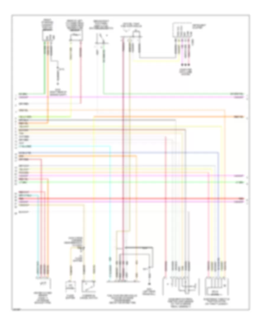
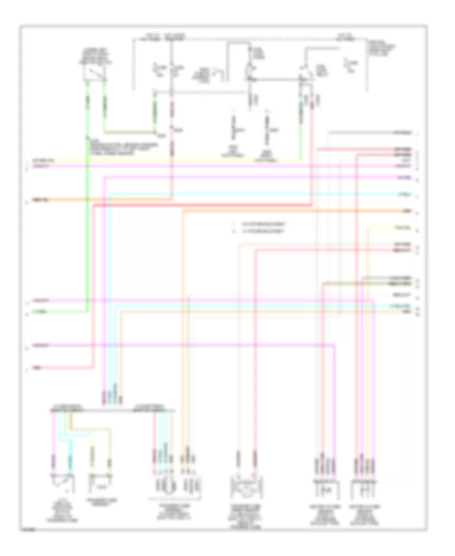
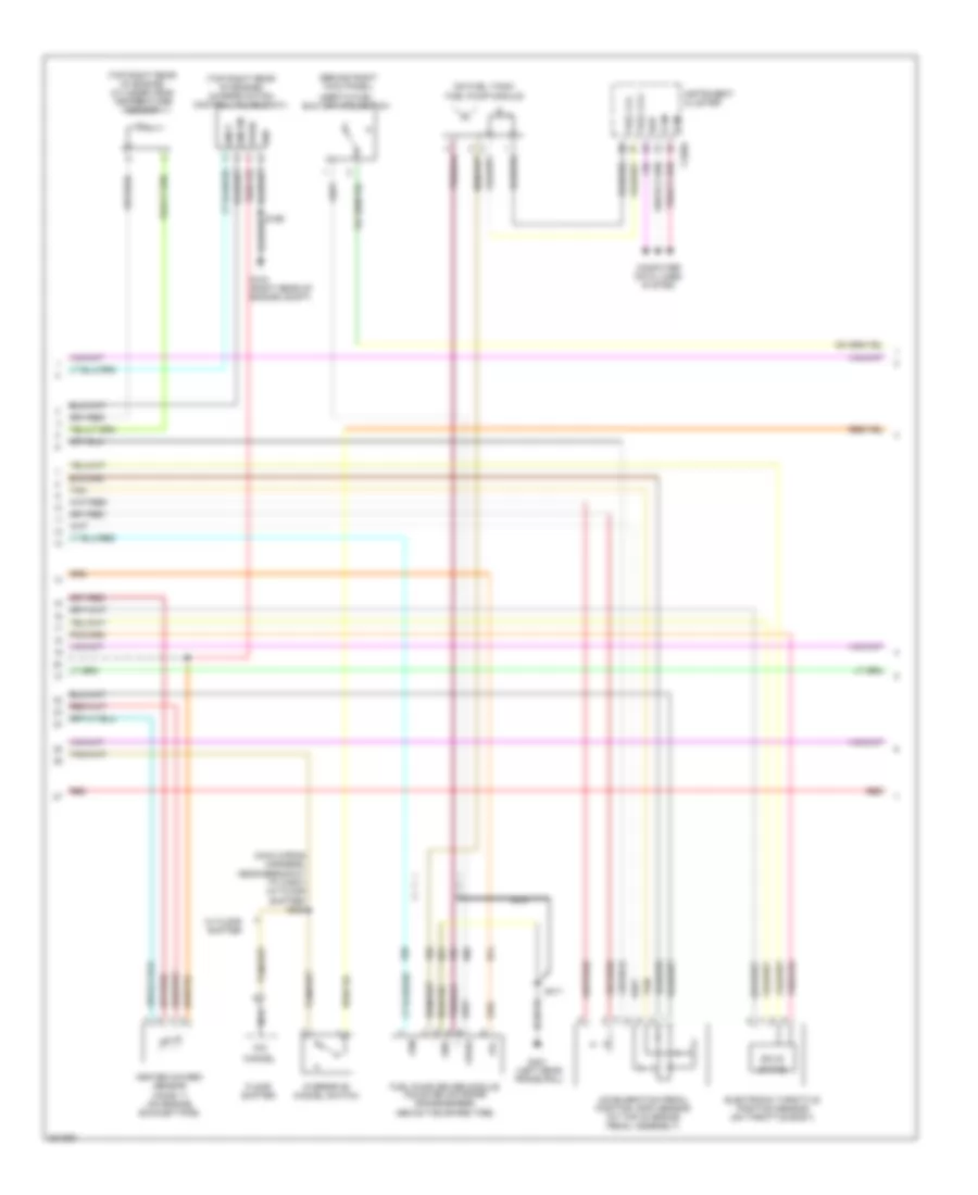
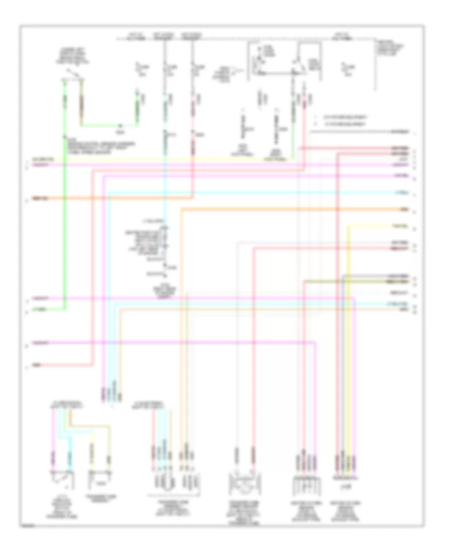
4.2L, Engine Performance Wiring Diagram (4 of 6) for Ford Pickup F150 2008
List of elements for 4.2L, Engine Performance Wiring Diagram (4 of 6) for Ford Pickup F150 2008:
- (behind right kick panel) inertia fuel shutoff (ifs) switch
- (front of engine) camshaft position sensor
- (main wiring harness, near breakout to c3007) s284
- (on fuel tank) fuel pump module
- (rear of left cylinder head) cylinder head temperature sensor
- Acceleration pedal position (app) sensor (at top of brake pedal assembly)
- C220a
- Can+
- Can-
- Cancel
- Computer data lines system
- Electronic throttle position motor (on throttle body)
- Floor shifter
- Fuel lvl+
- Fuel lvl-
- Fuel pump driver module (mounted on frame crossmember, above the spare tire)
- G103 (right rear of engine compt)
- G401 (left rear frame rail)
- Gnd
- Heated oxygen sensor (ho2s) 11 (on engine exhaust pipe)
- Instrument cluster
- Nca
- O/d
- Overdrive cancel switch
- Pwr
- Red
- S172
- S411
- Sig
- Solid
- State
- Tan
- Ubp
- W/ floor shifter
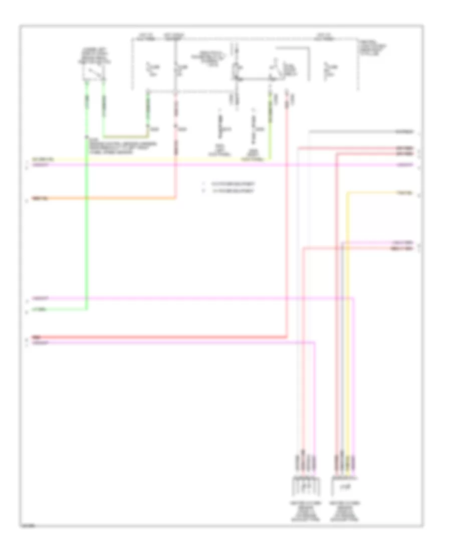
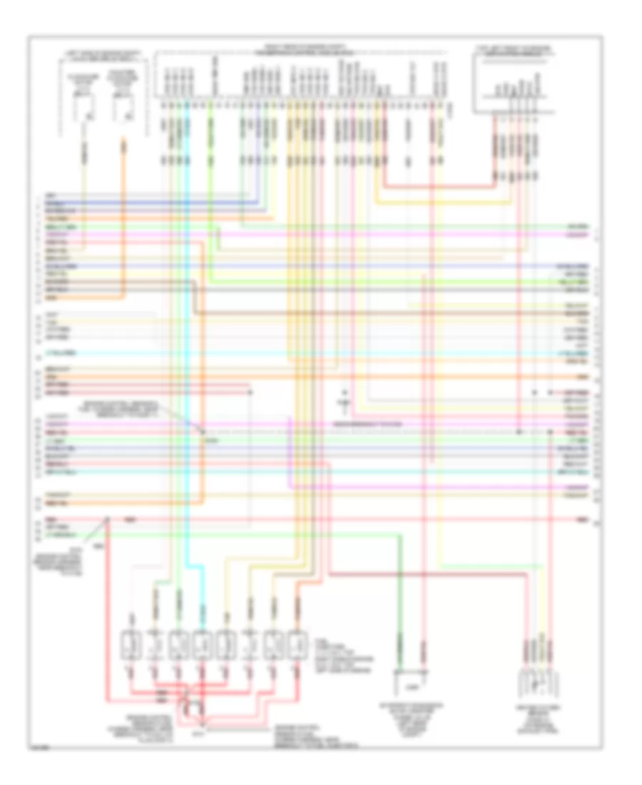
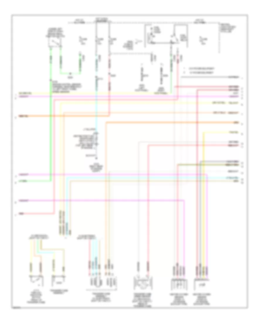
4.2L, Engine Performance Wiring Diagram (5 of 6) for Ford Pickup F150 2008
List of elements for 4.2L, Engine Performance Wiring Diagram (5 of 6) for Ford Pickup F150 2008:
- (under left side of dash) brake pedal position switch
- C270a red
- C270f
- Central junction box (near right "a" pillar)
- From pcm power relay a (diagram 1 of 6)
- Fuel pump relay
- Fuse 20a
- Fuse 5a
- G206 (right kick panel)
- G303 (left kick panel)
- Heated oxygen sensor (ho2s) 12 (on engine exhaust pipe)
- Heated oxygen sensor (ho2s) 22 (on engine exhaust pipe)
- Hot at all times
- Hot in run & start
- Red
- S109 (engine control sensor harness, near breakout to left front wheel speed sensor)
- S220
- S225
- S355
- W/ power equipment
- W/o power equipment
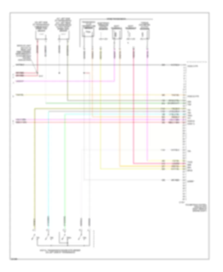
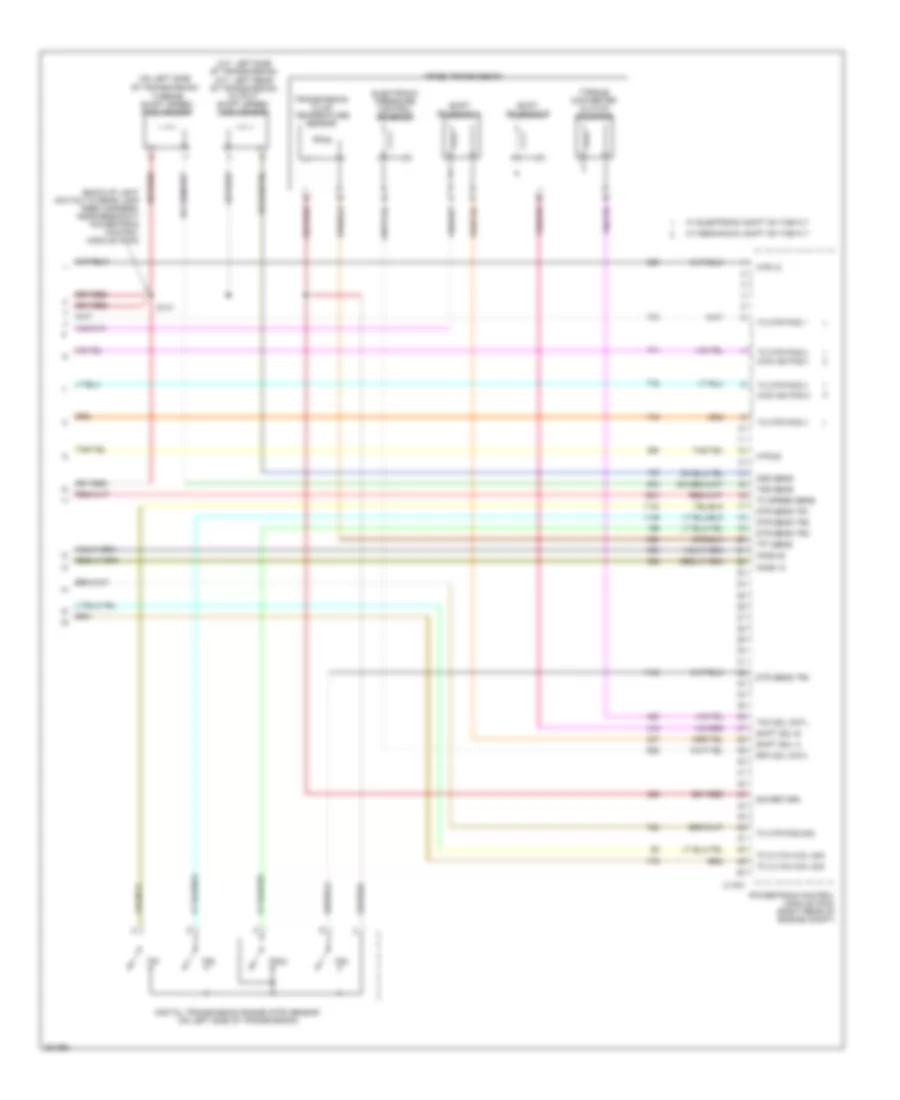
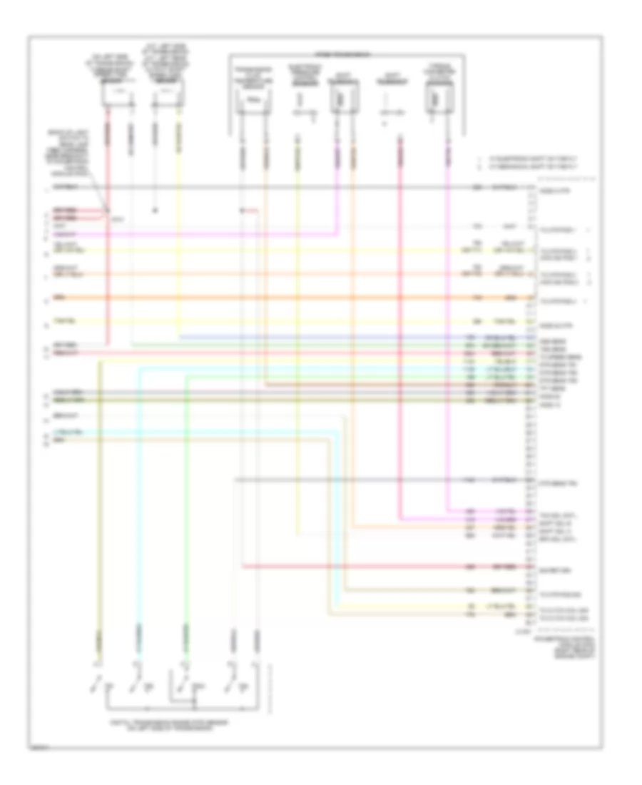
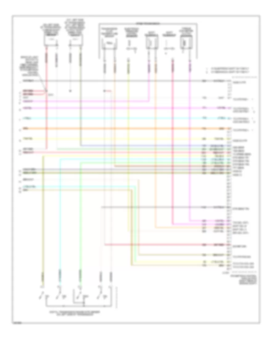
4.2L, Engine Performance Wiring Diagram (6 of 6) for Ford Pickup F150 2008
List of elements for 4.2L, Engine Performance Wiring Diagram (6 of 6) for Ford Pickup F150 2008:
- (a/t: left side of transmission) (m/t: left rear of transmission) output shaft speed (oss) sensor
- (back-up light switch to rear lamp feed harness, near breakout to powertrain control module (pcm))
- (on left side of transmission) turbine shaft speed (tss) sensor
- 4r75e transmission
- C175t
- Digital transmission range (dtr) sensor (on left side of transmission)
- Electronic pressure control solenoid
- Epcs
- Ho2s 12
- Ho2s 2 htr
- Ho2s 22
- Ho2s 22 htr
- Oss
- Powertrain control module (pcm) (right rear of engine compt)
- S141
- Shift solenoid a
- Shift solenoid b
- Sigret
- Ssa
- Ssb
- Tccs
- Tft
- Torque converter clutch solenoid
- Tr1
- Tr2
- Tr3a
- Tr4
- Transmission fluid temperature sensor
- Tss
4.6L
4.6L, Engine Performance Wiring Diagram (1 of 6) for Ford Pickup F150 2008
List of elements for 4.6L, Engine Performance Wiring Diagram (1 of 6) for Ford Pickup F150 2008:
- (engine control sensor & fuel charge harness, near breakout to c139)
- (engine control sensor harness, near breakout to c139)
- (evap) canister purge valve)
- (late production: engine control sensor harness, near breakout to left front wheel speed sensor)
- (near breakout to evaporative emission
- (near breakout to ho2s 12)
- (near breakout to integrated wheel ends solenoid)
- (right rear of engine compt) g102
- (right rear of engine compt) g103
- 4wd sw
- 4wdiwe
- 4wdmccw
- 4wdmcw
- A/c pressure transducer sensor (right front of engine compt)
- Accr
- Accs
- Acpt
- Air conditioning system
- Anti-lock brakes system
- Anti-theft system
- Apps 1
- Apps 2
- Apps 3
- Audio control module (acm) (behind center of dash)
- Boo
- Bps
- Bvref
- C175b
- C270b
- C270d
- C270g
- C290a
- Can bus +
- Can bus -
- Central junction box (cjb) (near right "a" pillar)
- Cltch pos botm
- Cltch pos sens
- Cooling fans system
- Cruise control system
- Data link connector (dlc) (under left side of dash)
- Etc module
- Etcref
- Evap can vnt vlv
- Evap canister vent control solenoid (vehicle underbody)
- Evmv
- Fc-v
- Feps
- Fss
- Ftpt sens sig
- Fuel pmp drv mod
- Fuel tank pressure sensor (at fuel tank)
- Fuse 10a
- Fuse 15a
- Fuse 5a
- Fuse 7.5a
- Generator com
- Generator mon
- Ground
- Hot at all times
- Hot in run or start
- Ign sw
- Integrated wheel ends solenoid (right rear of engine compt)
- Kapwr
- Led out
- Mass air flow/ intake air temp- erature sensor (top left front of engine)
- Pcm power relay
- Powertrain control module (pcm) (right rear of engine compt)
- Rdi
- Red
- Red/pnk
- Rly ctrl
- Rx in
- S102
- S104
- S105
- S106
- S107
- S113
- S117
- S118
- S140
- S177
- S199
- Sccs
- Sccsrtn
- Sig rtn
- Smc
- Starting/ charging system
- Starting/charging system
- Tan
- Tcs
- Tcss
- To fuel pump relay (diagram 5 of 6)
- Tracil
- Tx out
- V4wd
- Vbpwr
- Vpwr
- Vss
4.6L, Engine Performance Wiring Diagram (2 of 6) for Ford Pickup F150 2008
List of elements for 4.6L, Engine Performance Wiring Diagram (2 of 6) for Ford Pickup F150 2008:
- (cop) 1 cntl
- (cop) 2 cntl
- (cop) 3 cntl
- (cop) 4 cntl
- (cop) 5 cntl
- (cop) 6 cntl
- (cop) 7 cntl
- (cop) 8 cntl
- (cop) 8)
- (engine control sensor & fuel charge harness, near breakout to c139) s123
- (engine control sensor & fuel charge harness, near breakout to c139) s170
- (engine control sensor & fuel charge harness, near breakout to coil on plug (cop) 8)
- (engine control sensor & fuel charge harness, near breakout to fuel injector 3)
- (near crankshaft pulley) crankshaft position sensor
- (rear of left cylinder head) knock sensor
- (right rear of engine compt) powertrain control module (pcm)
- (top left side of engine) ignition transformer capacitor 2
- (top right side of engine) ignition transformer capacitor 1
- 2wd high
- 4wd high
- 4wd low
- C175e
- Cidrtn
- Coil on plug (1,2,3 & 4:top right side of engine) (5,6,7 & 8: top left side of engine)
- Dpfe
- Four-wheel drive switch
- Frpt sen sig
- Frt
- Fuel rail pressure temperature sensor (top front of engine)
- Heated positive crankshaft ventilation (pcv) valve
- Ho2s 11
- Ho2s 21
- Iat
- Maf
- Maf rtn
- Nca
- Pcvhc
- Power steering pressure sensor (w/ 4x4) (front of engine)
- Pspt
- Red
- S136 (engine control sensor & fuel charge harness, near breakout to coil on plug
- S161
- S162
- Shdrtn
- Solid state
- Tacm+
- Tan
4.6L, Engine Performance Wiring Diagram (3 of 6) for Ford Pickup F150 2008
List of elements for 4.6L, Engine Performance Wiring Diagram (3 of 6) for Ford Pickup F150 2008:
- (engine control sensor & fuel charge harness, near breakout to coil on plug (cop) 3)
- (engine control sensor & fuel charge harness, near breakout to fuel injector 8)
- (engine control sensor & fuel charge harness, near breakout to ho2s 11)
- (left side of engine compt) auxiliary relay box 1
- (near breakout to c139)
- (right rear of engine compt) powertrain control module (pcm)
- (top left front of engine) egr system module
- C175e
- Clockwise motor 4 x 4 relay
- Cmp sen
- Counter- clockwise motor 4 x 4 relay
- Crk sens +
- Crk sens -
- Dpfe
- Etc mtr +/-
- Evaporative emission (evap) canister purge valve (left rear of engine compt)
- Evr
- Fuel inj 1
- Fuel inj 2
- Fuel inj 3
- Fuel inj 4
- Fuel inj 5
- Fuel inj 6
- Fuel inj 7
- Fuel inj 8
- Fuel injectors (1, 2, 3 & 4: top right side of engine) (5, 6, 7 & 8: top left side of engine)
- Head tmp sen
- Heated oxygen sensor (ho2s) 21 (on engine exhaust pipe)
- Ho2s 11 htr
- Ho2s 21 htr
- Knk sen1 +
- Knk sen1 -
- Map
- Red
- Ref voltage
- S103 (engine control sensor harness, near breakout to c139)
- S129
- S131
- S135
- S154
- Sig return
- Sig rtn
- Tan
- Tan/red
- Tps ref vlt
- Tps sig 1
- Tps sig 2
- Tps sig rtn
- Vpwr
- Vref
4.6L, Engine Performance Wiring Diagram (4 of 6) for Ford Pickup F150 2008
List of elements for 4.6L, Engine Performance Wiring Diagram (4 of 6) for Ford Pickup F150 2008:
- (behind right kick panel) inertia fuel shutoff (ifs) switch
- (front of engine) camshaft position sensor
- (front of left cylinder head) cylinder head temperature sensor
- (main wiring harness, near breakout to c3007) s284
- (on fuel tank) fuel pump module
- Accelerator pedal position (app) sensor (at top of brake pedal assembly)
- C220a
- Can +
- Can -
- Cancel
- Computer data lines system
- Electronic throttle position sensor (on throttle body)
- Floor shifter
- Fpc
- Fpm
- Fuel level +
- Fuel level -
- Fuel pump driver module (mounted on frame crossmember, above the spare tire)
- G401 (left rear frame rail)
- Gnd
- Heated oxygen sensor (ho2s) 11 (on engine exhaust pipe)
- Instrument cluster
- Nca
- O/d
- Overdrive cancel switch
- Red
- S411
- Solid
- State
- Tan
- Ubp
- Vpwr
- W/ floor shifter
4.6L, Engine Performance Wiring Diagram (5 of 6) for Ford Pickup F150 2008
List of elements for 4.6L, Engine Performance Wiring Diagram (5 of 6) for Ford Pickup F150 2008:
- (diagram 1 of 6)
- (under left side of dash) brake pedal position switch
- 4 x 4 high/low indicator switch (front of transfer case)
- 4wdp1
- 4wdp2
- 4wdp3
- 4wdp4
- 4wdrtn
- All times
- C270a red
- C270f
- Central junction box (near right "a" pillar)
- From fuse 28 a
- Fuel pump diode
- Fuel pump relay
- Fuse 20a
- Fuse 5a
- G206 (right kick panel)
- G303 (left kick panel)
- Heated oxygen sensor (ho2s) 12 (on engine exhaust pipe)
- Heated oxygen sensor (ho2s) 22 (on engine exhaust pipe)
- Hot at
- Hot at all times
- Hot in run or start
- Red
- S109 (engine control sensor harness, near breakout to left front wheel speed sensor)
- S220
- S225
- S355
- Transfer case assembly
- Transfer case assembly (w/ electronic shift on the fly)
- Transfer case speed sensor (w/ mechanical shift on the fly) (rear of transfer case)
- W/ electronic shift on the fly
- W/ mechanical shift on the fly
- W/ power equipment
- W/o power equipment
4.6L, Engine Performance Wiring Diagram (6 of 6) for Ford Pickup F150 2008
List of elements for 4.6L, Engine Performance Wiring Diagram (6 of 6) for Ford Pickup F150 2008:
- (a/t: left side of transmission) (m/t: left rear of transmission) output shaft speed (oss) sensor
- (back-up light switch to rear lamp feed harness, near breakout powertrain control module (pcm))
- (on left side
- 4r75e transmission
- 4wd ind pos 1
- 4wd ind pos 2
- C175t
- Digital transmission range (dtr) sensor (on left side of transmission)
- Dtr sens tr1
- Dtr sens tr2
- Dtr sens tr3
- Dtr sens tr4
- Electronic pressure control solenoid
- Epc sol cntl
- Ho2s 12
- Ho2s 22
- Htr-12
- Htr-22
- Of transmission)
- Oss sens
- Powertrain control module (pcm) (right rear of engine compt)
- S141
- Shift sol a
- Shift sol b
- Shift solenoid a
- Shift solenoid b
- Sig return
- Tc cltch coil sig
- Tc mtr pos 1
- Tc mtr pos 2
- Tc mtr pos 3
- Tc mtr pos 4
- Tc mtr pos sig
- Tc speed sens
- Tcc sol cntl
- Tft sens
- Torque converter clutch solenoid
- Tr1
- Tr2
- Tr3a
- Tr4
- Transmission fluid temperature sensor
- Tss sens
- Turbine shaft speed (tss) sensor
- W/ electronic shift on the fly
- W/ mechanical shift on the fly
5.4L
5.4L, Engine Performance Wiring Diagram (1 of 6) for Ford Pickup F150 2008
List of elements for 5.4L, Engine Performance Wiring Diagram (1 of 6) for Ford Pickup F150 2008:
- (ccw) 4 x 4 relay
- (cw) 4 x 4 relay
- (engine control sensor & fuel charge harness, near breakout to c139)
- (engine control sensor harness, near breakout to c139)
- (late production: engine control sensor harness, near breakout to left front wheel speed sensor)
- (near breakout to
- (near breakout to evaporative
- (near breakout to ho2s 12)
- (right front of engine compt)
- (right rear of engine compt) g102
- (right rear of engine compt) g103
- 4 x 4 sol cntl
- 4wd sw
- A/c cltch prs sw
- A/c cltch rly
- A/c pressure transducer sensor
- Acpt
- Air conditioning system
- Airbag dep sig
- Anti-lock brakes system
- Anti-theft on ind
- Anti-theft system
- Apps sig 1
- Apps sig 2
- Apps sig 3
- Audio control module (acm)
- Aux spd cntl
- Boo
- C175b
- C270g red
- C290a
- Can bus +
- Can bus -
- Central junction box (near right "a" pillar)
- Cltch pos sens
- Cooling fans system
- Cruise control system
- Data link connector (dlc) (under left
- Deactivator sw
- Emission (evap) canister purge valve)
- Etc module
- Evap can vnt vlv
- Evap canister vent control solenoid (vehicle underbody)
- Evmv
- Fc-v
- Fss
- Ftpt sens sig
- Fuel pmp drv mod
- Fuel tank pressure sensor (at fuel tank)
- Fuse 10a
- Fuse 15a
- Fuse 5a
- Fuse 7.5a
- G103 (right rear of engine compt)
- Generator com
- Generator mon
- Ground
- Hot at all times
- Hot in run or start
- Ign sn
- Integrated wheel ends solenoid (right rear of engine compt)
- Integrated wheel ends solenoid)
- Kapwr
- Mass air flow/ intake air temperature sensor (top of engine)
- O/d cancel sw
- Pcm power relay
- Power
- Powertrain control module (pcm) (right rear of engine compt)
- Program sig
- Red
- Red/pnk
- Ref voltage
- Rly control
- Rx sig
- S102
- S104
- S105
- S107
- S113
- S117
- S118
- S140
- S177
- S199
- Side of dash)
- Sig rtn
- Smc
- Start relay
- Starting/ charging system
- Starting/charging system
- Tan
- To fuel pump relay (diagram 5 of 6)
- Tracil
- Tracs
- Tx sig
- Vbpwr
- Vpwr
- Vss
5.4L, Engine Performance Wiring Diagram (2 of 6) for Ford Pickup F150 2008
List of elements for 5.4L, Engine Performance Wiring Diagram (2 of 6) for Ford Pickup F150 2008:
- (cop) 1 cntl
- (cop) 2 cntl
- (cop) 3 cntl
- (cop) 4 cntl
- (cop) 5 cntl
- (cop) 6 cntl
- (cop) 7 cntl
- (cop) 8 cntl
- (cop) 8)
- (engine control sensor & fuel charge harness, near breakout
- (engine control sensor & fuel charge harness, near breakout to c139)
- (engine control sensor & fuel charge harness, near breakout to c139) s170
- (engine control sensor & fuel charge harness, near breakout to coil on plug
- (engine control sensor & fuel charge harness, near breakout to heated positive crankcase
- (near crankshaft pulley) crankshaft position sensor
- (right rear of engine compt) powertrain control module (pcm)
- (top left front of engine) ignition transformer capacitor 2
- (top left rear of engine)
- (top right of engine) ignition transformer capacitor 1
- (top right rear of engine) knock sensor 1
- 2wd high
- 4wd high
- 4wd low
- C175e
- Coil on plug (1,2,3 & 4: top right side of engine) (5,6,7 & 8: top left side of engine)
- Electronic throttle control (etc) motor (on throttle body)
- Etc mtr+/-
- Four-wheel drive switch
- Frpt sen sig
- Fuel rail pressure/ temperature sensor (top left side of engine)
- Ho2s 11
- Ho2s 21
- Iat
- Knk sen 2 +
- Knk sen 2 -
- Knock sensor 2
- Maf
- Maf rtn
- Nca
- Power steering pressure sensor (left front of engine)
- Psp sens
- Pwr
- Red
- S123
- S136
- S161
- S162
- Shd rtn
- Sig
- Sig rtn
- Tan
- Temp
- To coil on plug (cop) 3)
- Ventilation (pcv) valve)
- Vrsrtn 1
- Vrsrtn 2
5.4L, Engine Performance Wiring Diagram (3 of 6) for Ford Pickup F150 2008
List of elements for 5.4L, Engine Performance Wiring Diagram (3 of 6) for Ford Pickup F150 2008:
- (engine control sensor & fuel charge harness, near breakout to coil on plug (cop) 3)
- (engine control sensor & fuel charge harness, near breakout to fuel injector 8)
- (engine control sensor harness, near breakout to c139)
- (front of left cylinder head) camshaft position sensor 2
- (front of right cylinder head) camshaft position sensor 1
- (left side of engine compt) auxiliary relay box 1
- (near breakout to charge
- (right rear of engine compt) powertrain control module (pcm)
- C175e
- Clockwise motor 4 x 4 relay
- Cmcv mon
- Cmp sen 1
- Cmp sen 2
- Counter- clockwise motor 4 x 4 relay
- Crk sens +
- Crk sens -
- Electric fan clutch
- Etc mtr +/-
- Evaporative emission (evap) canister purge valve (left rear of engine compt)
- Fuel inj 1
- Fuel inj 2
- Fuel inj 3
- Fuel inj 4
- Fuel inj 5
- Fuel inj 6
- Fuel inj 7
- Fuel inj 8
- Fuel injectors (1, 2, 3, 4: top right side of engine) (5, 6, 7, 8: top left side of engine)
- Head tmp sen
- Heated oxygen sensor (ho2s) 21 (on engine exhaust pipe)
- Ho2s 11 htr
- Ho2s 21 htr
- Knk sen1 +
- Knk sen1 -
- Motion control valve (cmcv))
- Red
- Ref voltage
- S103
- S129
- S131
- S135 (engine control sensor & fuel charge harness, near breakout to fuel injector 8)
- S154
- Sig return
- Tan
- Tan/red
- Tps ref vlt
- Tps sig 1
- Tps sig 2
- Tps sig rtn
- Variable camshaft timing (vct) valve 1 (top right front of engine)
- Variable camshaft timing (vct) valve 2 (top left front of engine)
- Vct vlv 1
- Vct vlv 2
- Vpwr
5.4L, Engine Performance Wiring Diagram (4 of 6) for Ford Pickup F150 2008
List of elements for 5.4L, Engine Performance Wiring Diagram (4 of 6) for Ford Pickup F150 2008:
- (behind right kick panel)
- (main wiring harness, near breakout to c3007) (w/ floor shifter) s284
- (on fuel tank) fuel pump module
- (top right rear of engine) charge motion control valve (cmcv)
- (top right rear of engine) cylinder head temperature sensor
- Acceleration pedal position (app) sensor (at top of brake pedal assembly)
- C220a
- Can+
- Can-
- Cancel
- Cmcv
- Cmcvm
- Computer data lines system
- Electronic throttle position sensor (on throttle body)
- Floor shifter
- Fpc
- Fpm
- Fuel lvl+
- Fuel lvl-
- Fuel pump driver module (mounted on frame crossmember, above the spare tire)
- G103 (right rear of engine compt)
- G401 (left rear frame rail)
- Gnd
- Heated oxygen sensor (ho2s) 11 (on engine exhaust pipe)
- Inertia fuel shutoff (ifs) switch
- Instrument cluster
- Nca
- O/d
- Overdrive cancel switch
- Red
- S411
- Solid
- State
- Tan
- Ubp
- Vpwr
- W/ floor shifter
5.4L, Engine Performance Wiring Diagram (5 of 6) for Ford Pickup F150 2008
List of elements for 5.4L, Engine Performance Wiring Diagram (5 of 6) for Ford Pickup F150 2008:
- (pcv) valve (top left rear of engine)
- (under left side of dash) brake pedal position switch
- 4 x 4 high/low indicator switch (front of transfer case)
- 4wdp1
- 4wdp2
- 4wdp3
- 4wdp4
- 4wdrtn
- C270a red
- C270f
- Central junction box (near right "a" pillar)
- From fuse 28 (diagram 1 of 6)
- Fuel pump diode
- Fuel pump relay
- Fuse 10a
- Fuse 20a
- Fuse 5a
- G103 (right rear of engine compt)
- G206 (right kick panel)
- G303 (left kick panel)
- Heated oxygen sensor (ho2s) 12 (on engine exhaust pipe)
- Heated oxygen sensor (ho2s) 22 (on engine exhaust pipe)
- Heated positive crankcase ventilation
- Hot at all times
- Hot in run or start
- Red
- S109 (engine control sensor harness, near breakout to left front wheel speed sensor)
- S220
- S225
- S355
- Transfer case assembly
- Transfer case assembly (w/ electronic shift on the fly)
- Transfer case speed sensor (w/ mechanical shift on the fly) (rear of transfer case)
- W/ electronic shift on the fly
- W/ mechanical shift on the fly
- W/ power equipment
- W/o power equipment
5.4L, Engine Performance Wiring Diagram (6 of 6) for Ford Pickup F150 2008
List of elements for 5.4L, Engine Performance Wiring Diagram (6 of 6) for Ford Pickup F150 2008:
- (a/t: left side of transmission) (m/t: left rear of transmission) output shaft speed (oss) sensor
- (back-up light switch to rear lamp feed harness, near breakout to powertrain control module (pcm))
- (on left side of transmission) turbine shaft speed (tss) sensor
- (or 771)
- (or 772)
- 4r75e transmission
- 4wd ind pos 1
- 4wd ind pos 2
- C175t
- Digital transmission range (dtr) sensor (on left side of transmission)
- Dtr sens tr1
- Dtr sens tr2
- Dtr sens tr3
- Dtr sens tr4
- Electronic pressure control solenoid
- Epc sol cntl
- Ho2s 12
- Ho2s 2 htr
- Ho2s 22
- Ho2s 22 htr
- Oss sens
- Powertrain control module (pcm) (right rear of engine compt)
- S141
- Shift sol a
- Shift sol b
- Shift solenoid a
- Shift solenoid b
- Sig return
- Tc cltch coil sig
- Tc mtr pos 1
- Tc mtr pos 2
- Tc mtr pos 3
- Tc mtr pos 4
- Tc mtr pos sig
- Tc speed sens
- Tcc sol cntl
- Tft sens
- Torque converter clutch solenoid
- Tr1
- Tr2
- Tr3a
- Tr4
- Transmission fluid temperature sensor
- Tss sens
- W/ electronic shift on the fly
- W/ mechanical shift on the fly
5.4L FLEX FUEL
5.4L Flex Fuel, Engine Performance Wiring Diagram (1 of 6) for Ford Pickup F150 2008
List of elements for 5.4L Flex Fuel, Engine Performance Wiring Diagram (1 of 6) for Ford Pickup F150 2008:
- (ccw) 4 x 4 relay
- (cw) 4 x 4 relay
- (engine control sensor & fuel charge harness, near breakout to c139)
- (late production: engine control sensor harness, near breakout to left front wheel speed sensor)
- (near breakout to evaporative
- (near breakout to ho2s 12)
- (near breakout to integrated wheel ends solenoid)
- (right rear of engine compt) g102
- (right rear of engine compt) g103
- 4 x 4 sol cntl
- 4wd sw
- A/c cltch prs sw
- A/c cltch rly
- A/c pressure transducer sensor (right front of engine compt)
- Acpt
- Air conditioning system
- Airbag dep sig
- Anti-lock brakes system
- Anti-theft on ind
- Anti-theft system
- Apps sig 1
- Apps sig 2
- Apps sig 3
- Audio control module (acm) (behind center of dash)
- Aux spd cntl
- Boo
- C175b
- C270g red
- C290a
- Can bus +
- Can bus -
- Central junction box (near right "a" pillar)
- Compt)
- Cooling fans system
- Cpp-bt
- Cpp-tt
- Cruise control system
- Data link connector (dlc) (under left side of dash)
- Deactivator sw
- Emission (evap) canister purge valve)
- Etc module
- Evap can vnt vlv
- Evap canister vent control solenoid (vehicle underbody)
- Evmv
- Fc-v
- Fss
- Ftpt sens sig
- Fuel pmp drv mod
- Fuel tank pressure sensor (at fuel tank)
- Fuse 10a
- Fuse 15a
- Fuse 5a
- Fuse 7.5a
- G103 (right rear of engine
- Generator com
- Generator mon
- Ground
- Hot at all times
- Hot in run or start
- Ign sw
- Integrated wheel ends solenoid (right rear of engine compt)
- Kapwr
- Mass air flow/ intake air temperature sensor (top of engine)
- O/d cancel sw
- Pcm power relay
- Powertrain control module (pcm) (right rear of engine compt)
- Program sig
- Red
- Red/pnk
- Ref voltage
- Rly control
- Rx sig
- S102
- S104 (engine control sensor harness, near breakout to c139)
- S105
- S107
- S113
- S117
- S118
- S140
- S177
- S199
- Sig rtn
- Smc
- Start relay
- Starting/ charging system
- Starting/charging system
- Tan
- To fuel pump relay (diagram 5 of 6)
- Tracil
- Tracs
- Tx sig
- V4wd
- Vbpwr
- Vpwr
- Vss
5.4L Flex Fuel, Engine Performance Wiring Diagram (2 of 6) for Ford Pickup F150 2008
List of elements for 5.4L Flex Fuel, Engine Performance Wiring Diagram (2 of 6) for Ford Pickup F150 2008:
- (cop) 1 cntl
- (cop) 2 cntl
- (cop) 3 cntl
- (cop) 4 cntl
- (cop) 5 cntl
- (cop) 6 cntl
- (cop) 7 cntl
- (cop) 8 cntl
- (engine control sensor & fuel charge harness, near breakout
- (engine control sensor & fuel charge harness, near breakout to c139) s170
- (engine control sensor & fuel charge harness, near breakout to heated positive crankcase
- (near breakout to c139)
- (near crankshaft pulley) crankshaft position sensor
- (right rear of engine compt) powertrain control module (pcm)
- (top left front of engine) ignition transformer capacitor 2
- (top left rear of engine) knock sensor 2
- (top right of engine) ignition transformer capacitor 1
- (top right rear of engine) knock sensor 1
- 2wd high
- 4wd high
- 4wd low
- C175e
- Coil on plug (1,2,3 & 4: top right side of engine) (5,6,7 & 8: top left side of engine)
- Electronic throttle control (etc) motor (on throttle body)
- Etc mtr+/-
- Four-wheel drive switch
- Frpt sen sig
- Fuel rail pressure temperature sensor (top left side of engine)
- Ho2s 11
- Ho2s 21
- Iat
- Knk sen 2 +
- Knk sen 2 -
- Maf
- Maf rtn
- Nca
- Power steering pressure sensor (w/ 4x4) (left front of engine)
- Psp sens
- Red
- S123
- S136 (near breakout to coil on plug (cop) 8)
- S161
- S162
- Shdrtn
- Tan
- Temp
- To coil on plug (cop) 3)
- Ventilation (pcv) valve)
- Vrsrtn 1
- Vrsrtn 2
5.4L Flex Fuel, Engine Performance Wiring Diagram (3 of 6) for Ford Pickup F150 2008
List of elements for 5.4L Flex Fuel, Engine Performance Wiring Diagram (3 of 6) for Ford Pickup F150 2008:
- (engine control sensor & fuel charge harness, near breakout to coil on plug (cop) 3)
- (engine control sensor & fuel charge harness, near breakout to fuel injector 8)
- (engine control sensor harness, near breakout to c139)
- (front of left cylinder head) camshaft position sensor 2
- (front of right cylinder head) camshaft position sensor 1
- (left side of engine compt) (w/ electronic shift on the fly) auxiliary relay box 1
- (near breakout to charge motion control valve (cmcv))
- (near breakout to fuel injector 8)
- (right rear of engine compt) powertrain control module
- C175e
- Clockwise motor 4 x 4 relay
- Cmcv mon
- Cmp sen 1
- Cmp sen 2
- Counter- clockwise motor 4 x 4 relay
- Crk sens +
- Crk sens -
- Etc mtr +/-
- Evaporative emission (evap) canister purge valve (left rear of engine compt)
- Fuel inj 1
- Fuel inj 2
- Fuel inj 3
- Fuel inj 4
- Fuel inj 5
- Fuel inj 6
- Fuel inj 7
- Fuel inj 8
- Fuel injectors (1, 2, 3, 4: top right side of engine) (5, 6, 7: top left side of engine) (8: top left rear of of engine)
- Head tmp sen
- Heated oxygen sensor (ho2s) 21 (on engine exhaust pipe)
- Ho2s 11 htr
- Ho2s 21 htr
- Knk sen1 +
- Knk sen1 -
- Red
- Ref voltage
- S103
- S129
- S131
- S135
- S154
- Sig return
- Tan
- Tan/red
- Tps ref vlt
- Tps sig 1
- Tps sig 2
- Tps sig rtn
- Variable camshaft timing (vct) valve 1 (top right front of engine)
- Variable camshaft timing (vct) valve 2 (top left front of engine)
- Vct vlv 1
- Vct vlv 2
5.4L Flex Fuel, Engine Performance Wiring Diagram (4 of 6) for Ford Pickup F150 2008
List of elements for 5.4L Flex Fuel, Engine Performance Wiring Diagram (4 of 6) for Ford Pickup F150 2008:
- (behind right kick panel)
- (main wiring harness, near breakout to c3007) s284
- (on fuel tank) fuel pump module
- (top right rear of engine) charge motion control valve (cmcv)
- (top right rear of engine) cylinder head temperature sensor
- Ac/dc converter
- Acceleration pedal position (app) sensor (at top of brake pedal assembly)
- Batt svr rly
- Battery saver relay
- C220a
- C220b
- C431
- Can +
- Can -
- Cancel
- Central junction box (near right "a" pillar)
- Cmcv
- Cmcvm
- Computer data lines system
- Electronic throttle position sensor (on throttle body)
- Floor shifter
- Fpc
- Fpm
- Fuel level +
- Fuel level -
- Fuel pump driver module (mounted on frame crossmember, above the spare tire)
- Fuel pump module
- Fuse 15a
- G103 (right rear of engine compt)
- G401 (left rear frame rail)
- Gnd
- Heated oxygen sensor (ho2s) 11 (on engine exhaust pipe)
- Hot at all times
- Inertia fuel shutoff (ifs) switch
- Instrument cluster
- Nca
- O/d
- Overdrive cancel switch
- Red
- S240 (body main wiring harness, in breakout to c219)
- S411
- Solid
- State
- Tan
- Ubp
- Vpwr
- W/ floor shifter
5.4L Flex Fuel, Engine Performance Wiring Diagram (5 of 6) for Ford Pickup F150 2008
List of elements for 5.4L Flex Fuel, Engine Performance Wiring Diagram (5 of 6) for Ford Pickup F150 2008:
- (under left side of dash) brake pedal position switch
- 4 x 4 high/low indicator switch (front of transfer case)
- 4wdp1
- 4wdp2
- 4wdp3
- 4wdp4
- 4wdrtn
- C270a red
- C270f
- Central junction box (near right "a" pillar)
- From fuse 28 a (diagram 1 of 6)
- Fuel pump diode
- Fuel pump relay
- Fuse 10a
- Fuse 20a
- Fuse 5a
- G103 (right rear of engine compt)
- G206 (right kick panel)
- G303 (left kick panel)
- Heated oxygen sensor (ho2s) 12 (on engine exhaust pipe)
- Heated oxygen sensor (ho2s) 22 (on engine exhaust pipe)
- Heated positive crankcase ventilation (pcv) valve (top left rear of engine)
- Hot at all times
- Hot in run or start
- Red
- S109 (engine control sensor harness, near breakout to left front wheel speed sensor)
- S199
- S220
- S225
- S355
- Transfer case assembly
- Transfer case assembly (w/ electronic shift on the fly)
- Transfer case speed sensor (w/ mechanical shift on the fly) (rear of transfer case)
- W/ electronic shift on the fly
- W/ mechanical shift on the fly
- W/ power equipment
- W/o power equipment
5.4L Flex Fuel, Engine Performance Wiring Diagram (6 of 6) for Ford Pickup F150 2008
List of elements for 5.4L Flex Fuel, Engine Performance Wiring Diagram (6 of 6) for Ford Pickup F150 2008:
- (a/t: left side of transmission) (m/t: left rear of transmission) output shaft speed (oss) sensor
- (back-up light switch to rear lamp feed harness, near breakout to powertrain control module (pcm))
- (on left side of transmission) turbine shaft speed (tss) sensor
- 4r75e transmission
- 4wd ind pos 1
- 4wd ind pos 2
- C175t
- Digital transmission range (dtr) sensor (on left side of transmission)
- Dtr sens tr1
- Dtr sens tr2
- Dtr sens tr3
- Dtr sens tr4
- Electronic pressure control solenoid
- Epc sol cntl
- Ho2s 12
- Ho2s 2 htr
- Ho2s 22
- Ho2s 22 htr
- Oss sens
- Powertrain control module (pcm) (right rear of engine compt)
- S141
- Shift sol a
- Shift sol b
- Shift solenoid a
- Shift solenoid b
- Sig return
- Tc cltch coil sig
- Tc mtr pos 1
- Tc mtr pos 2
- Tc mtr pos 3
- Tc mtr pos 4
- Tc mtr pos sig
- Tc speed sens
- Tcc sol cntl
- Tft sens
- Torque converter clutch solenoid
- Tr1
- Tr2
- Tr3a
- Tr4
- Transmission fluid temperature sensor
- Tss sens
- W/ electronic shift on the fly
- W/ mechanical shift on the fly