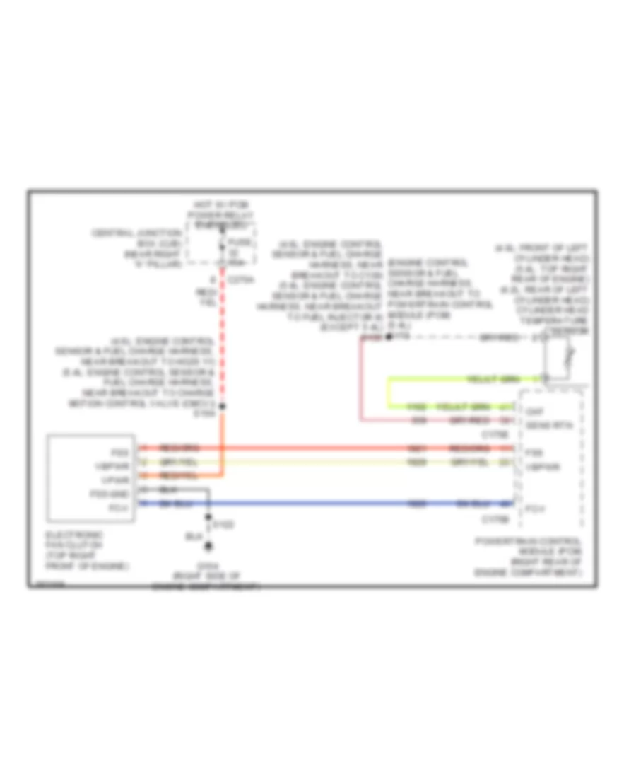
COOLING FAN
Cooling Fan Wiring Diagram for Ford Pickup F150 2008
List of elements for Cooling Fan Wiring Diagram for Ford Pickup F150 2008:
- (4.6l: engine control sensor & fuel charge (engine control harness, near sensor & fuel breakout to c139) charge harness, (5.4l: engine control near breakout to sensor & fuel charge powertrain control harness, near breakout module (pcm) to fuel injector 8) (5.4l) (except 5.4l) s173 s135
- (4.6l: engine control sensor & fuel charge harness, near breakout to ho2s 11) (5.4l: engine control sensor & fuel charge harness, near breakout to charge motion control valve (cmcv)) s154
- (4.6l: front of left cylinder head) (5.4l: top right rear of engine) (4.2l: rear of left cylinder head) cylinder head temperature sensor
- C175b
- C175e
- C270a
- Central junction box (cjb) (near right "a" pillar)
- Cht
- Electronic fan clutch (top right front of engine)
- Fc-v
- Fss
- Fss-gnd
- Fuse 15a
- G104 (right side of engine compartment)
- Hot w/ pcm power relay energized
- Powertrain control module (pcm) (right rear of engine compartment)
- S122
- Sens rtn
- Vbpwr
- Vpwr
 English