ANTI-LOCK BRAKES
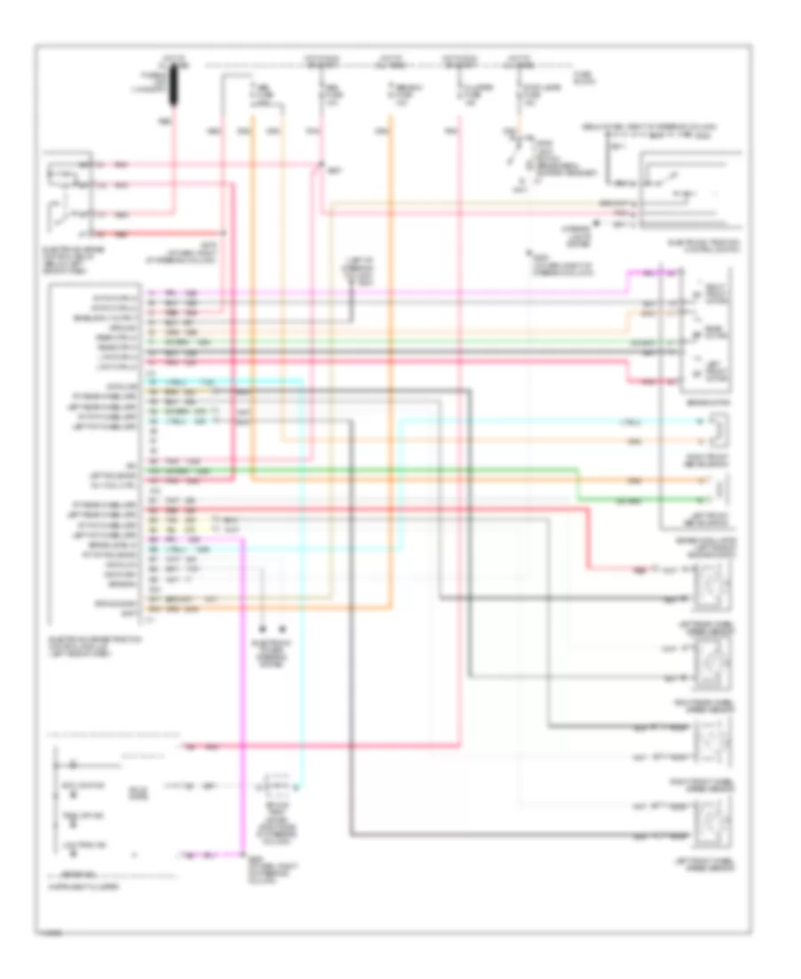
Anti-lock Brake Wiring Diagrams, Bosch for Oldsmobile Intrigue GLS 1999

List of elements for Anti-lock Brake Wiring Diagrams, Bosch for Oldsmobile Intrigue GLS 1999:
- (base of steering column) g202
- (not used)
- (on brake pedal bracket)
- +5v ref
- A11
- Anti lock ind
- B c1
- Battery
- Body control module (behind left side of dash)
- Brake pressure modulator valve
- C 1995 vftc
- Cluster fuse 10a
- Data link connector (below left side of dash)
- Electronic brake traction control module (left side of engine compt)
- Electronic power steering system
- Electronic power steering system
- Electronic traction control switch
- Fuse block
- G102 (left front strut tower)
- G205
- Ground
- Hot at all times
- Hot in run or start
- Ignition
- Instrument cluster
- Interior lights system
- Left front wheel speed sensor
- Left rear wheel speed sensor
- Lf whl spd
- Low trac ind
- Lr whl spd
- Msva high
- Msva low
- Nca
- Pnk
- Powertrain control module (left front of engine compt)
- Pump motor
- Pump mtr ctrl
- Red
- Req tps sig
- Rf whl spd
- Right front wheel speed sensor
- Right rear wheel speed sensor
- Rr whl spd
- S205 (i/p harn, right of steering column)
- S211
- Serial data
- Solid state
- Splice pack sp205 (taped in harness, right of steering column)
- Stop lamp fuse 15a
- Stop lamp switch
- Stop lp feed
- Strg pos
- Tach out c2
- Tach signal
- Tan
- Tcs signal
- Tire infl reset
- Torque del c2
- Torque req c1
- Trac input
- Trac off ind
- Trans abs fuse 26 10a
- Underhood accessory wiring junction block
- Warning systems
Anti-lock Brake Wiring Diagrams, Delco for Oldsmobile Intrigue GLS 1999
List of elements for Anti-lock Brake Wiring Diagrams, Delco for Oldsmobile Intrigue GLS 1999:
- (below dash, right of steering column)
- (left of steering column) g204
- A10
- A11
- A12
- Abs fuse 10a
- Abs fuse 20a
- Abs-bcm fuse 10a
- Anti lock ind
- B10
- B11
- B12
- Batt
- Brake in
- Brake ind
- Brake level in
- Brake modulator (left side of engine compt)
- Brake motor
- C1 stop lamp switch (brake pedal support bracket)
- Cluster fuse 10a
- Data line
- Electronic brake control relay (below left side of dash)
- Electronic brake traction control module (left side of dash)
- Electronic power steering system
- Electronic traction control switch
- Enable rly output
- Ets mode sw
- Fuse block
- G205
- Ground
- Hot at all times
- Hot in run or start
- Ign
- Instrument cluster
- Interior lights system
- L fnt mtr-hi
- L fnt mtr-lo
- Left fnt wheel spd
- Left front abs solenoid
- Left front motor
- Left front wheel speed sensor
- Left rear wheel spd
- Left rear wheel speed sensor
- Left solenoid
- Low trac ind
- Msva high
- Msva low
- Nca
- Pnk
- Rear motor
- Rear mtr-hi
- Rear mtr-lo
- Red
- Right front abs solenoid
- Right front motor
- Right front wheel speed sensor
- Right rear wheel speed sensor
- Rly coil ctrl
- Rt fnt mtr-hi
- Rt fnt mtr-lo
- Rt fnt solenoid
- Rt fnt wheel spd
- Rt rear wheel spd
- S205 (i/p harn, right of steering column)
- S211
- S279 (i/p harn, right of steering column)
- S286 (i/p harn, right of steering column)
- S287
- Solid state
- Splice pack (sp205) (right side of steering column)
- Stop lamps fuse 15a
- Tan
- Trac off ind