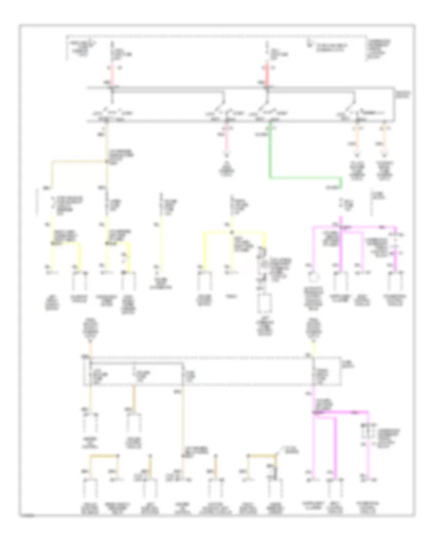
POWER DISTRIBUTION
Power Distribution Wiring Diagram (1 of 3) for Oldsmobile Intrigue GLS 1999

List of elements for Power Distribution Wiring Diagram (1 of 3) for Oldsmobile Intrigue GLS 1999:
- (body harn, below passenger seat)
- (c67)
- (i/p harn, right side of dash) s293
- (i/p harness, 21 cm from bulkhead grommet) s275
- (i/p harness, right of steering column)
- 3.5l
- 3.8l
- A/c clu fuse 10a
- A/c clu relay
- A12
- Abs-bcm fuse 10a
- Accessory power receptacle
- B12
- Bat 1 maxi fuse 60a
- Bat 2 maxi fuse 60a
- Bat 3 maxi fuse 60a
- Battery
- Blower motor control module
- Blower motor resistor
- Body control module
- C2 a1 c12 (cj2)
- C67
- Cd changer fuse 10a
- Cd player
- Cigar lighter
- Cigar ltr fuse 20a
- Cj2
- Cool fan 1 maxi fuse 40a
- Cool fan 1 relay
- Cool fan 2 maxi fuse 30a
- Cool fan 2 relay
- Cool fan 3 relay
- Crank maxi fuse 40a
- Crank relay
- Data link connector
- Daytime running lamp control module
- Door lock relay
- Door locks fuse 20a
- Driver seat adjuster switch
- Ecm fuse 10a
- Electronic brake and traction control module
- Electronic brake control relay
- Electronic brake traction control module
- F/pmp fuse 15a
- F/pmp relay
- From a remote battery stud (diagram 1 of 3)
- From bat 2 maxi fuse (diagram 1 of 3)
- Fuel tank filler door lock relay
- Fuse block
- Fusible link (10 ga- rust)
- G201 (behind right side of dash)
- Gen fuse 10a
- Generator
- Hazard fuse 15a
- Hazard warning switch
- Hdlp l fuse 15a
- Hdlp r fuse 15a
- Headlamp switch
- Heater- a/c control
- High blower fuse 25a
- Horn fuse 15a
- Horn relay
- Inadv power bus fuse 15a
- Instrument cluster
- Left headlamp
- Low frequency audio amplifier
- Lp park fuse 20a
- Nca
- Outside remote control rearview mirror switch
- Passenger seat adjuster switch
- Power drop connector
- Power mirrors fuse 2a
- Power seats circuit breaker 30a
- Powertrain control module
- R/cmpt rel fuse 7.5a
- Radio
- Radio- hvac fuse 15a
- Rear defogger circuit breaker 30a
- Rear window defogger relay
- Red
- Remote battery stud
- Remote control door lock receiver
- Right headlamp
- S202
- S230
- S269 (i/p harness, near blower motor)
- Starter
- Stop lamp switch
- Stop lamps fuse 15a
- To hdlp l fuse (diagram 1 of 3)
- To high blower fuse (diagram 1 of 3)
- To ign 1 maxi fuse (diagram 2 of 3)
- Transaxle range switch
- Underhood accessory wiring junction block
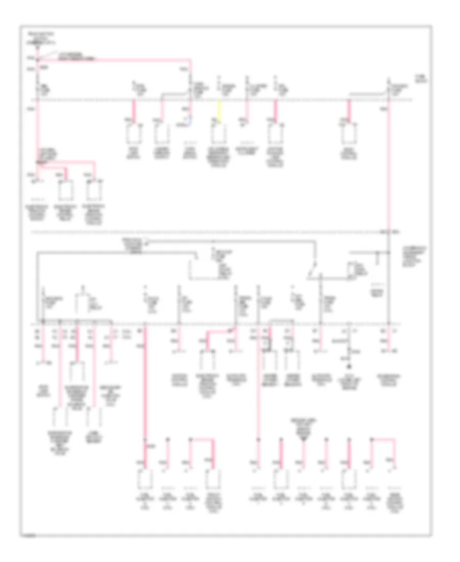
Power Distribution Wiring Diagram (2 of 3) for Oldsmobile Intrigue GLS 1999
List of elements for Power Distribution Wiring Diagram (2 of 3) for Oldsmobile Intrigue GLS 1999:
- (body harn, under right front seat) s310
- (cj2) (c67)
- (i/p harn, behind left side of dash)
- (i/p harn, left side of dash) s234
- (i/p harness, below radio) s233
- (i/p harness, left side of dash) s249
- (i/p harness, near blower motor) s263
- Accy
- Automatic transaxle control position indicator bulb
- Body control module
- C1 a
- C1 b
- C1 c
- C1 e
- C13
- C2 a
- C2 b
- C5 b7
- Crank signal fuse 10a
- Cruise control module
- Cruise control switch
- Cruise fuse 10a
- Daytime running lamp control module
- From gen d fuse (diagram 1 of 3)
- From ignition switch (diagram 2 of 3)
- Fuse block
- G nca
- Heater- a/c control
- Hvac fuse 10a
- Ign 0 fuse 10a
- Ign 1 maxi fuse 30a
- Ign 2 maxi fuse 50a
- Ignition switch
- Inflatable restraint steering wheel module coil
- Inside rearview mirror
- Instrument cluster
- Left electric actuator
- Left front window switch
- Left steering wheel control switch
- Lock
- Low blower fuse 20a
- Nca
- Nca g
- Pnk
- Power drop connector
- Power drop fuse 10a
- Powertrain control module
- Pwr windows pwr sunroof circuit breaker 30a
- Radio
- Radio cruise fuse 2a
- Rear window defogger relay
- Red
- Right electric actuator
- Run
- S227 (i/p harn, right side of dash)
- S270
- Start
- Sunroof module
- To crank signal fuse (diagram 2 of 3)
- To ign main relay (diagram 3 of 3)
- To low blower fuse (diagram 2 of 3)
- To s228 (diagram 3 of 3)
- Underhood accessory wiring junction block
- Vacuum electric solenoid
- W/ 3.5l engine
- Wind- shield wiper/ washer switch
- Windshield wiper motor
- Wiper fuse 25a
Power Distribution Wiring Diagram (3 of 3) for Oldsmobile Intrigue GLS 1999
List of elements for Power Distribution Wiring Diagram (3 of 3) for Oldsmobile Intrigue GLS 1999:
- (3.5l)
- (3.8l)
- (diagram 2 of 3)
- (engine harn, top left side of engine) s109
- (i/p harn, left side of dash) s287
- (i/p harness, right side of dash)
- A/c clu relay
- Abs fuse 10a
- Air bag fuse 15a
- Air pump fuse 30a
- Air pump relay (3.5l)
- Automatic transaxle (3.5l)
- Automatic transaxle (3.8l)
- Body control module
- Btsi fuse 10a
- C12
- Cluster fuse 10a
- Crank relay
- Daytime running lamp control module
- Dfi fuse 15a (3.8l)
- Drl fuse 10a
- Electronic brake control relay
- Electronic brake traction control module
- Electronic brake/ traction control module (3.5l)
- Electronic traction control switch
- Eng emis fuse 10a
- Evaporative emissions canister purge solenoid valve
- Evaporative emissions canister vent solenoid valve
- F/injr fuse 15a
- F/injr fuse 15a (3.5l)
- From ign 2 maxi fuse e
- From ignition switch (diagram 2 of 3)
- Front ignition control module (3.5l)
- Fuel injector
- Fuel injector (3.5l)
- Fuel injector (3.8l)
- Fuse block
- G110 (lower left front of engine)
- Hazard warning switch
- Heated oxygen sensor 1
- Heated oxygen sensor 2
- Ign main relay
- Ignition control module
- Inflatable restraint sensing and diagnostic module
- Instrument cluster
- Mass air flow sensor
- Nca
- Oxy sen fuse 15a
- Pcm-bcm fuse 10a
- Pnk
- Powertrain control module
- Rear ignition control module (3.5l)
- S106
- S169
- S228
- Secondary air injection valve (3.5l)
- Stop lamp switch
- Trans fuse 10a (3.8l)
- Trans/ abs fuse 10a (3.5l)
- Turn signal switch
- Turn signals fuse 10a
- Underhood accessory wiring junction block