CRUISE CONTROL
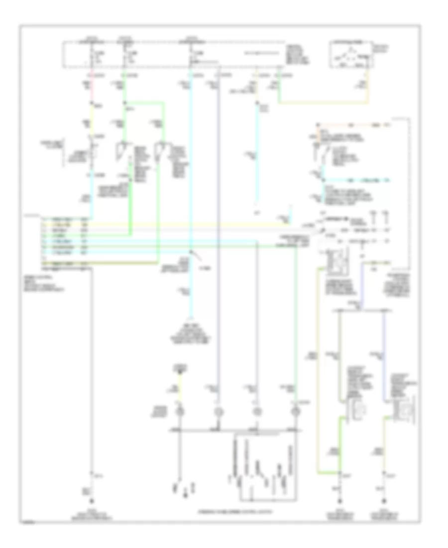
Cruise Control Wiring Diagram for Ford Escape 2003
List of elements for Cruise Control Wiring Diagram for Ford Escape 2003:
- (near breakout to left side turn signal lamp)
- (on right rear of transmission, near left axle flange) output shaft speed sensor
- (on right side of transmission) vehicle speed sensor
- 2.0l
- 3.0l
- A/t
- Abs test connector (on left side of engine compartment, near strut tower)
- Acc
- Air bag sliding contact
- Brake pedal position switch (on bracket, above brake pedal)
- C218a
- C220b
- C220c
- C270a
- C270c
- C270d
- C270e
- Central junction box (cjb) (below left end of dash)
- Clutch switch (on bracket, above clutch pedal)
- Coast
- Deact- ivator switch (on bracket, above brake pedal)
- Fuse 10a
- Fuse 15a
- Fuse 5a
- G101 (top center of transmission)
- G103 (right front of engine compartment)
- Horn
- Horns system
- Hot at all times
- Hot in start or run
- Ignition switch
- Instrument cluster
- Limited
- M/t
- Nca
- Near breakout to c263)
- Off
- Powertrain control module (pcm) (in recess on upper center of firewall)
- Rest
- Resume
- Run
- S1002
- S107
- S114
- S119 (near breakout for left headlamp)
- S137 (2.0l)
- S139 (near breakout for left front park/turn lamp)
- S222
- S314
- Set/accelerate
- Sound systems
- Speed control servo (on right side of engine compartment)
- Speed control indicator
- Speed control off
- Speed control on
- Start
- Steering wheel/speed control switch
- Turbine shaft speed sensor (on right rear of transmission)
- W/ abs
 English