SUPPLEMENTAL RESTRAINTS
Supplemental Restraints Wiring Diagram for Ford Escape 2003
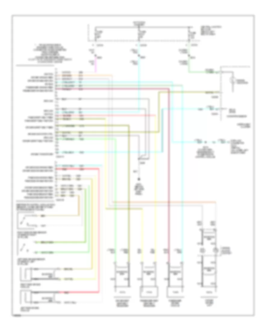
List of elements for Supplemental Restraints Wiring Diagram for Ford Escape 2003:
- Air bag indicator
- Air bag indicator ctrl
- Air bag sliding contact
- Air bag tone driver
- C2041a
- C2041b
- C220a
- C220b
- C270c
- C270d
- Central junction box (cjb) (below left end of dash)
- Data link connector (dlc) (partial) (on lower left side of dash)
- Driver air bag feed
- Driver air bag return
- Driver air bag unit
- Driver safety belt feed
- Driver safety belt return
- Driver seat seat belt tensioner
- Driver side air bag feed
- Driver side air bag return
- Driver side sensor feed
- Driver side sensor return
- Fuse f2.4 10a
- Fuse f2.5 5a
- Fuse f2.7 10a
- G203 (behind left side dash panel)
- Ground
- Hot in run or start
- Ignition
- Instrument cluster
- Iso bus
- Left side air bag module
- Left side air bag sensor (at base of left "b" pillar)
- Microprocessor
- Nca
- Pass safety belt feed
- Pass safety belt return
- Pass side air bag feed
- Pass side air bag return
- Pass side sensor feed
- Pass side sensor return
- Passenger air bag feed
- Passenger air bag module
- Passenger air bag return
- Passenger seat seat belt tensioner
- Pin shorting bar is engaged when module connector is disconnected from harness (shorting bar is connected between pins: 3-4, 6-7, 15-16, 18-22 & 20-21 conn. c2041a 2-3 & 5-6 conn. c2041b)
- Red
- Restraints control module (rcm) (beneath lower center of dash, on transmission tunnel)
- Right side air bag module
- Right side air bag sensor (at base of right "b" pillar)
- S205
- S208
- S215
- S219 (in main harn, near breakout to restraints control module)
- S225
- Shorting bar
- Solid state
 English