ENGINE PERFORMANCE
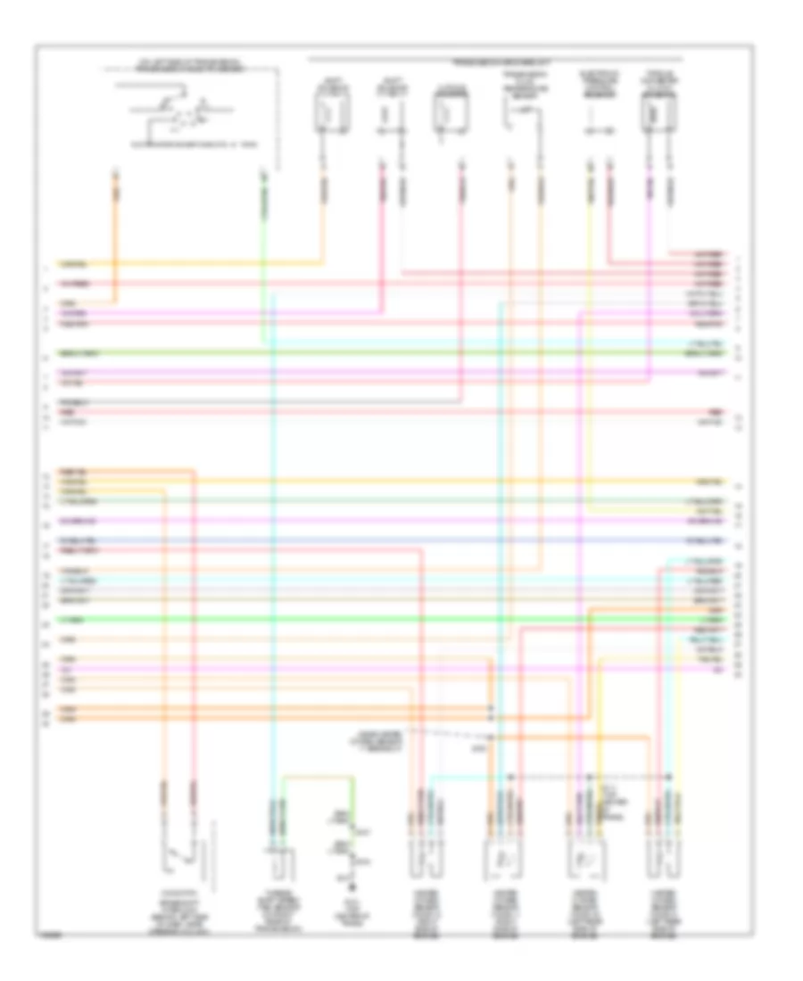
2.0L
2.0L, Engine Performance Wiring Diagram (1 of 3) for Ford Escape 2003

List of elements for 2.0L, Engine Performance Wiring Diagram (1 of 3) for Ford Escape 2003:
- (on lower left side of dash) data link connector (dlc)
- (on lower left side of engine block) crankshaft position sensor
- A/c system
- Battery junction box (bjb) (on left front corner of engine compt)
- C175
- C251
- Cht
- Ckp sens
- Cooling fans system
- Cruise control system (speed control servo)
- Dual press
- Eeprom
- Fp driver
- Fuel gauge sensor
- Fuel pump
- Fuel pump relay
- Fuel tank unit (beneath left rear of vehicle, in fuel tank)
- Fuse 20a
- G100 (center rear of engine compt)
- G101 (top center of trans)
- G203 (behind left side of dash)
- G402 (left rear end of vehicle)
- Ground
- High fan
- Ho2s 12
- Hot at all times
- Ign coil
- Ignition coil
- Ignition transformer capacitor 1 (on rear of cyl head)
- Inertia fuel shutoff (ifs) switch (at base of right door pillar, near kick panel)
- Inj 3
- Maf
- Med fan
- Nca
- O/d sw sig
- Plugs
- Powertrain control module (pcm) (in recess on upper center of firewall)
- Psp sw
- Red
- Rx cntl
- S101
- S102
- S104
- S106
- S107
- S112
- S113
- S138 (near left front park/turn lamp breakout)
- S205
- S206 (near instrument cluster breakout)
- S207 (near instrument cluster breakout)
- S309
- Scp bus +
- Scp bus -
- Sens ret
- Shift interlock system
- Shift sol b
- Start rly
- Starting system
- Tft sen v ref
- To spark
- Transmissions system
- Tur shaft ss
- Tx sig
- Vss out
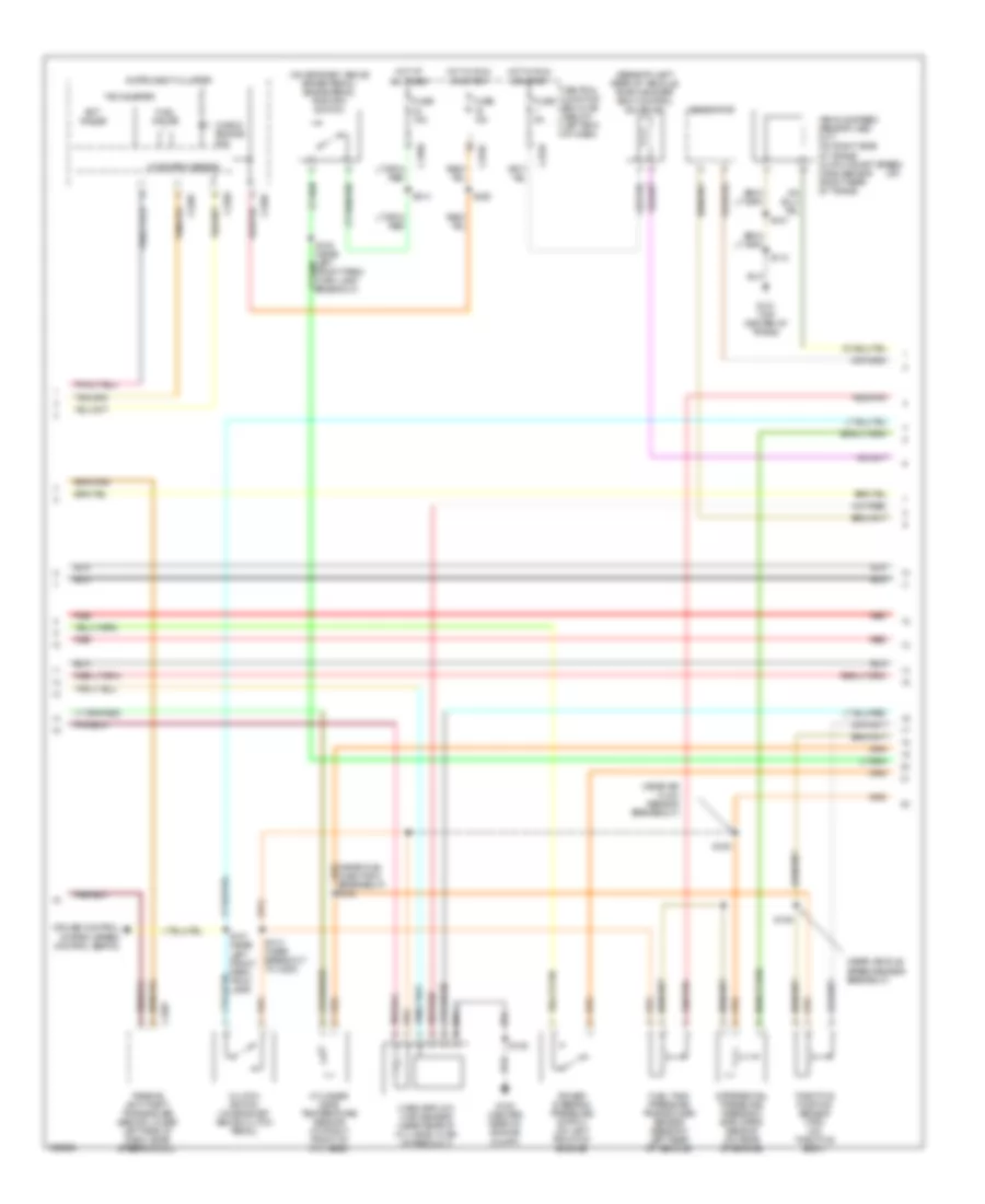
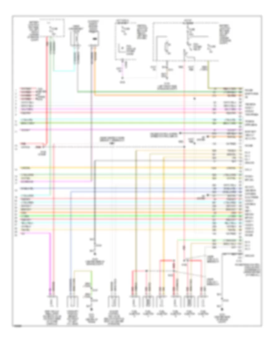
2.0L, Engine Performance Wiring Diagram (2 of 3) for Ford Escape 2003
List of elements for 2.0L, Engine Performance Wiring Diagram (2 of 3) for Ford Escape 2003:
- (a/t)
- (beneath left rear of vehicle) evap canister vent control solenoid
- (near air flow sensor breakeout)
- (near fuel injector 4 breakeout) s154
- (near vehicle speed sensor breakout)
- (on bracket, above brake pedal) brake pedal position switch
- C2007
- C220a
- C220c
- C270c
- C270e
- C270f
- Central junction box (cjb) (below left end of dash)
- Check engine ind
- Clutch switch (on bracket, above clutch pedal)
- Cruise control system (speed control servo)
- Cylinder head temperature sensor (on right front of cyl head)
- Differential pressure feedback egr (dpfe) sensor (on rear of engine)
- Ect gauge
- Fuel gauge
- Fuel tank pressure transducer sensor (beneath left rear of vehicle)
- Fuse 10a
- Fuse 15a
- Fuse 5a
- G100 (center rear of engine compt)
- G101 (top center of trans)
- Generator
- Hot at all times
- Hot in run or start
- Instrument cluster
- Mass airflow (maf) sensor (near rear of cyl head, in air intake duct)
- Microprocessor
- Passive anti-theft transceiver (behind lower left side of dash, near steering col)
- Power steering pressure switch (on left front of engine)
- Red
- Red/pnk
- S105
- S106
- S107
- S109
- S112
- S137 (near left front park/ trun lamp)
- S222
- S313 (near breakout to c263)
- S314
- Tachometer
- Throttle position sensor (tps) (on throttle body)
- Vehicle speed sensor (vss) (m/t) (on right side of trans) output shaft speed (oss) sensor (right rear of trans)
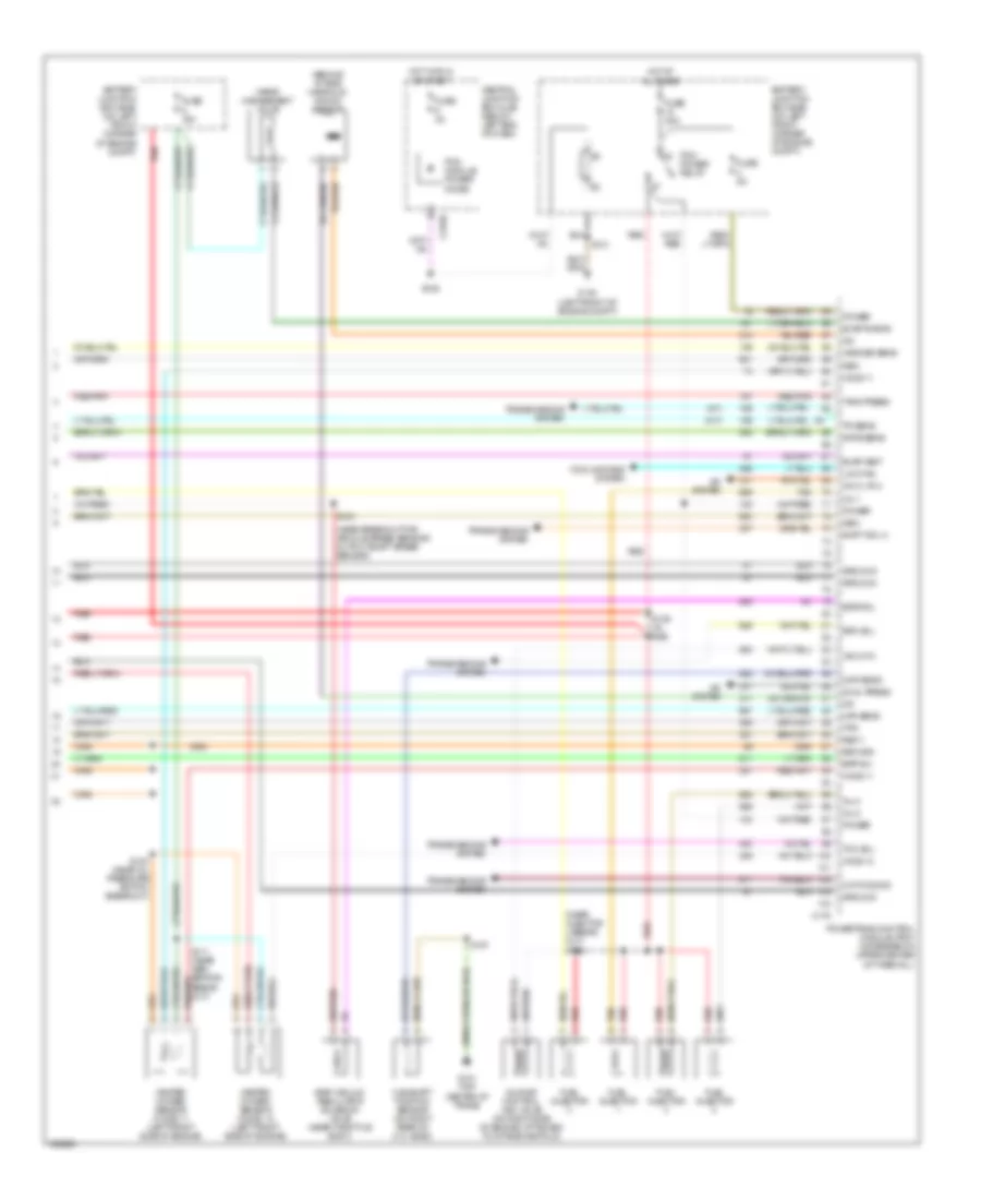
2.0L, Engine Performance Wiring Diagram (3 of 3) for Ford Escape 2003
List of elements for 2.0L, Engine Performance Wiring Diagram (3 of 3) for Ford Escape 2003:
- (a/t)
- (behind intake manifold) knock sensor
- (m/t)
- (near breakout for vehicle speed sensor/ output shaft speed sensor)
- (near injector 4 break- out) s152
- 3-2t/ccs sig
- A/c cltch
- A/c system
- Battery junction box (bjb) (on left front corner of engine compt)
- Bpp sw
- C175
- C270b
- Camshaft position sensor (on right rear of cyl head)
- Central junction box (cjb) (below left end of dash)
- Cmp sens
- Cooling fans system
- Dpfe sens
- Dual press
- Egr sol
- Egr vacuum regulator solenoid valve (near throttle body)
- Epc sol
- Evap purge
- Evap vent
- Fuel injector
- Fuse 15a
- Fuse 30a
- Fuse 3a
- Fuse 5a
- G101 (top center of trans)
- G104 (left front of engine compt)
- Gen
- Ground
- Heated oxygen sensor (ho2s) 11 (left front side of engine)
- Heated oxygen sensor (ho2s) 12 (left front side of engine)
- Ho2s 11
- Ho2s 12
- Hot at all times
- Hot in run or start
- Iac cntl
- Idle air control (iac) valve (on right side of engine, attached to intake manifold)
- Inj 1
- Inj 2
- Inj 4
- Low fan
- Maf sens
- Pcm module power diode
- Pcm power relay
- Power
- Powertrain control module (pcm) (in recess on upper center of firewall)
- Red
- Red/pnk
- Ref v
- Return
- S100 (near oil pressure switch breakout)
- S103
- S107
- S111 (near gen- erator break- out)
- S128
- S129 (in bjb)
- S131
- Shift sol a
- Tan
- Tank press
- Tcc sol
- Tps
- Tr sens
- Transmissions system
- Vapor management valve
- Vss/oss sens
3.0L
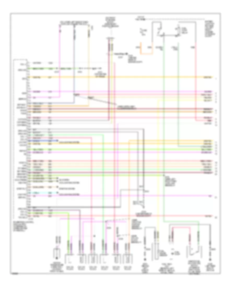
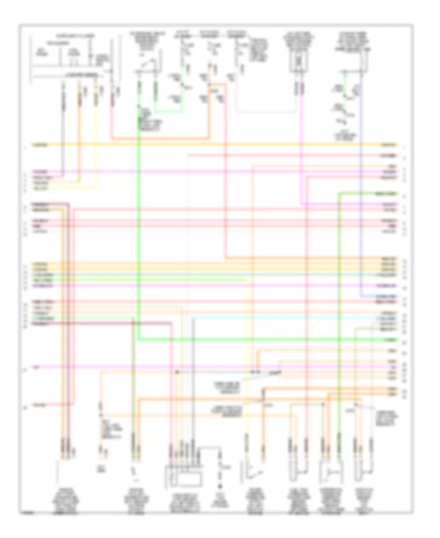
3.0L, Engine Performance Wiring Diagram (1 of 4) for Ford Escape 2003
List of elements for 3.0L, Engine Performance Wiring Diagram (1 of 4) for Ford Escape 2003:
- (near coil on plug 6 breakout)
- (near instrument cluster breakout)
- (near throttle position sensor breakout)
- (on front of engine block) crankshaft position sensor
- (on lower left side of dash) data link connector (dlc)
- 3-2t/ccs
- A/c system
- Battery junction box (bjb) (on left front corner of engine compt)
- C175
- C251
- Ckp sens
- Coil 1
- Coil 2
- Coil 4
- Coil 5
- Coil 6
- Coil on plug 1
- Coil on plug 2
- Coil on plug 3
- Coil on plug 4
- Coil on plug 5
- Coil on plug 6
- Cooling fans system
- Dual press
- Ect sens
- Eeprom
- Egr sol
- Fp driver
- Fuel gauge sensor
- Fuel pump
- Fuel pump relay
- Fuel tank unit (beneath left rear of vehicle, in fuel tank)
- Fuse 20a
- G100 (center rear of engine compt)
- G101 (top center of trans)
- G203 (behind left side of dash)
- G402 (left rear end of vehicle)
- Ground
- High fan
- Ho2s 12
- Hot at all times
- Ignition transformer capacitor 1 (on right front of eng)
- Inertia fuel shutoff (ifs) switch (at base of right door pillar, near kick panel)
- Low fan
- Maf
- Med fan
- Nca
- O/d sw
- Powertrain control module (pcm) (in recess on upper center of firewall)
- Psp sw
- Red
- Rx sig
- S104
- S107
- S138 (near left front park/ turn lamp breakout)
- S155
- S156
- S157
- S205
- S206
- S207
- S309
- Scp bus +
- Scp bus -
- Sens ret
- Ss a
- Ss b
- Start rly
- Starting system
- Tcc sol
- Tft sens
- Tx sig
3.0L, Engine Performance Wiring Diagram (2 of 4) for Ford Escape 2003
List of elements for 3.0L, Engine Performance Wiring Diagram (2 of 4) for Ford Escape 2003:
- (near egr vacuum reg sol valve breakout)
- (near mass air flow sensor breakout)
- (near throttle position sensor breakout)
- (on bracket, above brake pedal) brake pedal position switch
- (on left side of engine compt) evap canister vent control solenoid
- (on right rear of trans, near left axle flange) output shaft speed sensor (oss)
- C2007
- C220a
- C220c
- C248
- C270c
- C270e
- C270f
- Central junction box (cjb) (below left end of dash)
- Check engine ind
- Differential pressure feedback egr (dpfe) sensor (on right rear of engine)
- Ect gauge
- Engine coolant temperature (ect) sensor (on rear of right cyl head)
- Fuel gauge
- Fuel tank pressure transducer sensor (beneath left rear of vehicle)
- Fuse 10a
- Fuse 15a
- Fuse 5a
- G101 (top center of trans)
- Hot at all times
- Hot in run or start
- Instrument cluster
- Mass airflow (maf) sensor (on left side of engine compt, in air intake duct)
- Microprocessor
- Not used
- Passive anti-theft transceiver (behind lower left side of dash, near steering col)
- Power steering pressure switch (on left front of engine)
- Red
- Red/pnk
- S104
- S105
- S106
- S107
- S109
- S154
- S222
- S313 (tail lamp harn, near c263 breakout)
- S314
- Tachometer
- Throttle position sensor (tps) (on throttle body)
3.0L, Engine Performance Wiring Diagram (3 of 4) for Ford Escape 2003
List of elements for 3.0L, Engine Performance Wiring Diagram (3 of 4) for Ford Escape 2003:
- (near heated oxygen sensor 11 breakout)
- (on left side of transmission) transmission range (tr) sensor
- 3-2t/ccs solenoid
- Brake shift interlock (behind left side of dash, near steering column)
- Electronic pressure control solenoid
- G101 (top center of trans)
- Heated oxygen sensor (ho2s) 11 (right side of engine)
- Heated oxygen sensor (ho2s) 12 (right side of engine)
- Heated oxygen sensor (ho2s) 21 (left rear side of engine)
- Heated oxygen sensor (ho2s) 22 (left rear side of engine)
- O/d switch
- Red
- Red/pnk
- S100
- S104
- S107
- S111 (top center of trans)
- Shift solenoid a
- Shift solenoid b
- Torque converter clutch solenoid
- Transmission fluid temperature sensor
- Transmission hardware unit
- Turbine shaft speed (tss) sensor (on right rear of transmission)
3.0L, Engine Performance Wiring Diagram (4 of 4) for Ford Escape 2003
List of elements for 3.0L, Engine Performance Wiring Diagram (4 of 4) for Ford Escape 2003:
- (near fuel inj 1 breakout)
- (near fuel inj 2 breakout)
- (near heated oxygen sensor 11 breakout) s103
- (on right side of engine) knock sensor
- (top center of trans) s108
- A/c cltch
- A/c system
- Battery junction box (bjb) (on left front corner of engine compt)
- Bpp sw
- C175
- C270b
- Camshaft position sensor (on front of left cyl head)
- Central junction box (cjb) (below left end of dash)
- Cmp sens
- Coil 3
- Cruise control system (speed control servo)
- Dpfe sens
- Dual press
- Egr vacuum regulator solenoid valve (on right rear of intake manifold)
- Epc sol
- Evap purge
- Evap vent
- Fp driv
- Fuel injector
- Fuse 15a
- Fuse 30a
- Fuse 3a
- Fuse 5a
- G100 (center rear of engine compt)
- G101 (top center of trans)
- G104 (left front side of engine compt)
- Ground
- Ho2s 11
- Ho2s 12
- Ho2s 21
- Ho2s 22
- Hot at all times
- Hot in run or start
- Iac cntl
- Idle air control (iac) valve (below throttle body, on center of engine)
- Inj 1
- Inj 2
- Inj 3
- Inj 4
- Inj 5
- Inj 6
- Maf sens
- Oss sens
- Pcm module power diode
- Pcm power relay
- Power
- Powertrain control module (pcm) (in recess on upper center of firewall)
- Red
- Red/pnk
- Ref v
- Return
- S102
- S104
- S106
- S107
- S128
- S129 (in bjb)
- S131
- S152
- S153
- Tan
- Tank press
- Tps
- Tr sens
- Tss sens
- Vapor management valve
- Vss out