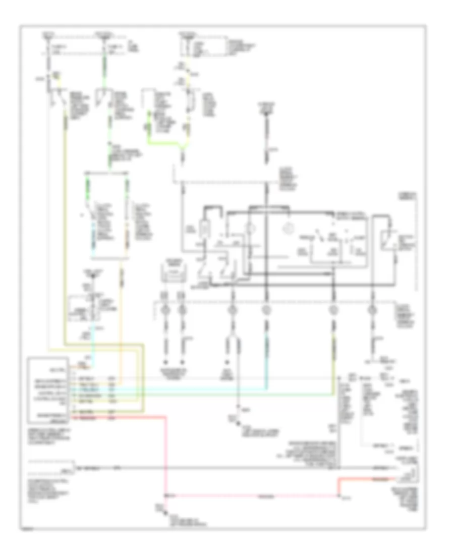
CRUISE CONTROL
Cruise Control Wiring Diagram for Ford Ranger 1997
List of elements for Cruise Control Wiring Diagram for Ford Ranger 1997:
- (engine sensor harness, 2.3l: near breakout to throttle position sensor; 3.0l: left rear of engine compt; 4.0l: near breakout to fuel injector 6) s111
- 1.4k ohms
- 15a
- 7.5a
- A/t
- Accel
- Anti- theft system
- Brake on/off (boo) switch (on brake pedal support)
- Brake press in
- Brake pressure switch (left side of engine compart- ment)
- C214
- C215
- C219
- C221
- C224
- C409
- Clock- spring assembly (top of steering column)
- Clutch pedal position (cpp) switch (top of clutch pedal support)
- Clutch pedal position (cpp) switch jumper (left of steering column)
- Coast
- Control sw gnd
- Control sw in
- Driver's airbag
- Engine compartment fuse/relay box
- Fuse 10
- Fuse 13
- G104 (top center of left fender apron)
- G108 (left side of upper radiator support)
- Generic electronic module (gem)/ central timer module (ctm) (behind center of i/p)
- Ground
- Horn maxi fuse 11 20a
- Horn nca switches
- Horn relay (in eng compt fuse/ panel)
- Hot at all times
- Hot in run
- I/p fuse panel
- Ign
- Ignition key warning switch
- Ind ctrl
- Instru- ment cluster
- Instrument cluster
- Interior lights system
- M/t
- Main light switch
- Nca
- Off
- Ohms
- Powertrain control module (pcm) (right rear of engine compartment, through safety wall)
- Remote anti- theft person- ality (rap) module (left rear corner of cab)
- Resume
- S110
- S135
- S136
- S139 (dash to head- lamp harn, left side of safety wall)
- S141
- S205
- S229 (main harness, behind top left side of i/p)
- Set/
- Speed control ind
- Speed control servo/ amplifier assembly (right rear of engine compartment)
- Speed control switch assembly
- Speedo
- Steering assembly
- Vehicle speed in
- Vehicle speed sensor (vss) (left rear of trans/ transfer case)
- Vss in
 English