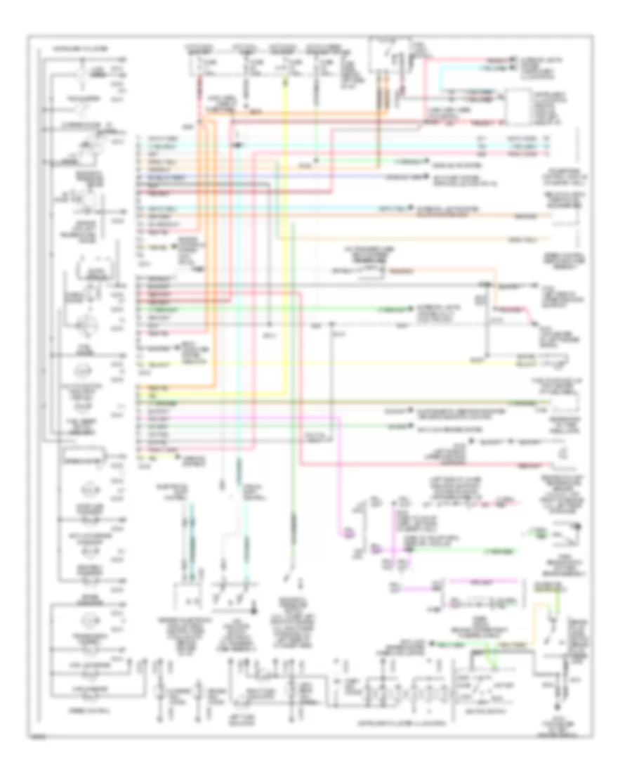
INSTRUMENT CLUSTER
Instrument Cluster Wiring Diagram for Ford Ranger 1997
List of elements for Instrument Cluster Wiring Diagram for Ford Ranger 1997:
- (below glv box) inertia fuel shut-off (ifs)
- (dash to hdlmp harn, near drl module) s120
- (left side of lower radiator support) daytime running lamps (drl) module
- (main harn, near i/p fuse panel)
- (main harn, near i/p fuse pnl) s208
- (on transfer case) vehicle speed sensor (vss)
- 3.0l/4.0l only
- 4.32k ohms
- 4w- abs
- 4wd hi range
- 4wd low range
- 4x4 indicator switch (top front of transfer case assembly)
- Acc
- Air bag indi- cator
- Anti-lock brake indicator
- Anti-lock brakes system
- Anti-lock brakes system (rabs module pin2)
- Anti-theft system (rap module c409, pin 16)
- Body computer system (gem/ctm)
- Brake fluid level switch (brake fluid reser- voir)
- Brake indicator
- C168
- C214
- C215
- C216
- C223
- Charge gauge
- Charge indi- cator
- Check gauge
- Door ajar indicator
- Electronic shift control
- Engine controls system (pcm pin 48)
- Engine coolant temperature gauge
- Engine coolant temperature sender (3.0l/4.0l: top front of engine; 2.3l: left rear of engine)
- Engine oil pressure gauge
- Engine oil pressure switch (4.0l: lower left front of engine; 3.0l: right rear of engine; 2.3l: left rear of cylinder head)
- Exterior lights (system multi- function sw)
- Exterior lights system multi-function sw)
- Fuel gauge
- Fuel pump module (top center of fuel tank)
- Fuel reset switch indicator
- Fuse 15a
- Fuse 7.5a
- G104 (top center of left fender apron)
- G108 (left side of upper radiator support)
- Generator/ voltage regulator
- Generic electronic module (gem)/ central timer module (ctm) (behind center of i/p)
- Gnd
- Head
- Headlights system
- High beam indi- cator
- Hot at all times
- Hot in hi beam or flash to pass
- Hot in run or start
- I/p fuse panel (behind left side of i/p)
- Ignition switch
- Instrument cluster
- Instrument cluster illumination
- Instrument illumination dimming module (top left side of i/p)
- Interior lights system (instrument illumination)
- Left turn indicator
- Lock
- Main light switch
- Manual shift control
- Multi-function indicator lamp (mil)
- Off
- Ohms
- Park
- Park brake switch (on park brake assembly)
- Powertrain control module (at saftey wall)
- Rabs
- Rabs diode (engine compartment fuse/relay box)
- Red
- Right turn indicator
- Run
- S1007
- S110
- S120 (dash to hdlmp harn, left side of safety wall)
- S122
- S131
- S205
- S214
- S219
- S229
- S237
- S240
- S244
- Seat belt indicator
- Slosh module
- Speed control
- Speed control servo/amplifier assembly
- Speedometer
- Start
- Tachometer
- Theft indi- cator
- Transmission control
- W/ drl
- W/o drl
- Warning systems
 English