TRANSMISSION
2.3L
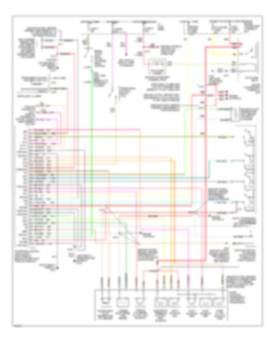
2.3L, Transmission Wiring Diagram, 4R44E for Ford Ranger 1997

List of elements for 2.3L, Transmission Wiring Diagram, 4R44E for Ford Ranger 1997:
- (dash panel to headlamp junction harness, near breakout to left headlamp)
- (engine control sensor extension harness, near breakout to harness in-line connector, left rear of engine)
- (engine control sensor harness, near breakout to ground g123)
- (engine control sensor harness, near breakout to intake air temp (iat) sensor)
- (engine control sensor harness, near breakout to throttle position (tp) sensor)
- (left side of upper radiator support) g108
- (power for heated oxygen sensors)
- (right side of firewall) g123
- (top center of left fender apron) g104
- 4r44e automatic transmission (left side of transmission)
- Boo
- Brake on/off (boo) switch (on brake pedal support)
- C111
- C214
- C216
- Case gnd
- Ccs
- Coast clutch solenoid (css)
- Cse gnd
- Digital transmission range sensor (left side of trans)
- Dlc
- Dlc (+)
- Dlc (-)
- Drl module, backup lamps, dtr sensor
- Ect
- Electronic pressure control (epc) solenoid
- Engine compartment fuse/relay box
- Engine controls
- Engine controls (ignition coil, radio noise capacitor)
- Engine coolant temperature (ect) sensor (top right front of eng, in water outlet tube)
- Epc
- Fuse 13 15a
- Fuse 19 25a
- Fuse 26 10a
- G108 (left side of upper radiator support)
- Ho2s fuse 3 15a
- Hot at all times
- Hot in run
- Hot in start or run
- I/p fuse panel
- Instrument cluster
- Kapwr
- Malfunction indicator lamp (mil)
- Memory power fuse 5 15a
- Mil
- O/d off
- Pcm power diode
- Pcm power fuse 2 30a
- Pcm power relay
- Power
- Powertrain control module (pcm) (right rear of engine compartment, through firewall)
- Pwr gnd
- R p
- Red
- S100
- S1002
- S102
- S103
- S104
- S106
- S110
- S111
- S121
- S147
- S228 (main harn, near breakout to instrument cluster)
- Shift solenoid (ss1)
- Shift solenoid (ss2)
- Shift solenoid (ss3)
- Sig rtn
- Ss1
- Ss2
- Ss3
- Tcc
- Tcil
- Tcs
- Tft
- Throttle position (tp) sensor (top right side of engine, on throttle body)
- Torque converter clutch (tcc) solenoid
- Tr1
- Tr2
- Tr4
- Transmission control indicator lamp (tcil)
- Transmission control switch (tcs)
- Transmission fluid temperature (tft) sensor
- Tss
- Turbine shaft speed (tss) sensor
- Vehicle speed sensor (vss) (left rear of transmission) (4x2 models) (left rear of transfer case) (4x4 models)
- Vref
- Vss
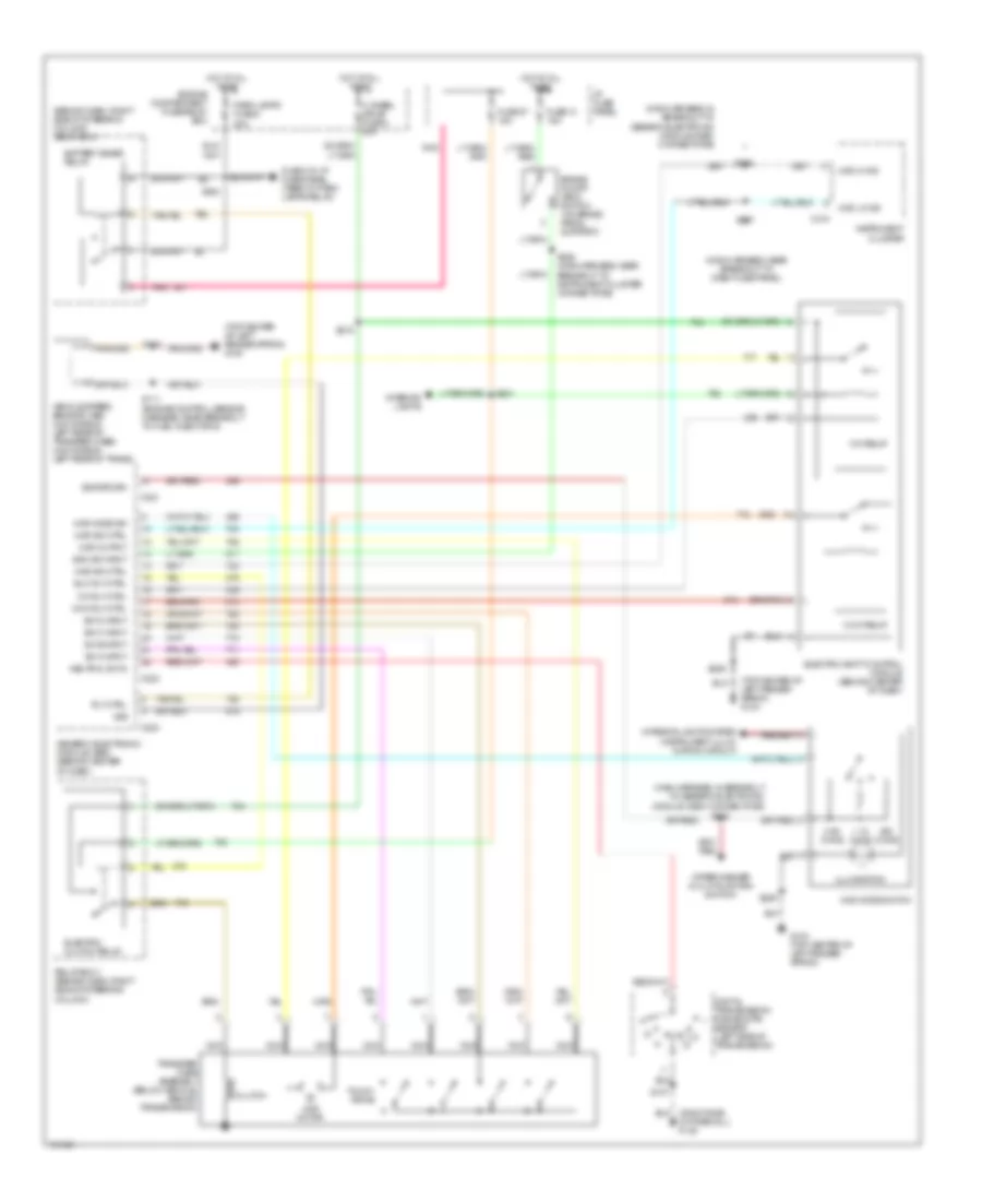
Transfer Case Wiring Diagram for Ford Ranger 1997
List of elements for Transfer Case Wiring Diagram for Ford Ranger 1997:
- (behind dash, right side of steering column) relay box 1
- (main harness, in breakout to generic electronic module (gem) connectors)
- (main harness, near breakout to dash fuse panel)
- (top center of left fender apron) g104
- 1.1k ohms
- 3.9k ohms
- 4 wheel drive fuse 4 20a
- 4wd hi ind
- 4wd ind ctrl
- 4wd lo ind
- 4wd mode sw
- 4wd mode switch
- 4wd motor
- 4wd output
- Battery saver relay
- Boo sw input
- Brake on/off (boo) switch (on brake pedal support)
- C214
- C221
- C223
- C224
- Ccw relay
- Ccw rly ctrl
- Clutch
- Cw relay
- Cw rly ctrl
- Digital transmission range (dtr) sensor (left side of transmission)
- Elc rly ctrl
- Electric clutch relay
- Electric shift control module (behind center of dash)
- Engine compartment fuse/relay box
- Fuse 13 15a
- Fuse 27 15a
- Fuse 3 in i/p fuse panel (feed to park lamps relay)
- G104 (top center of left fender apron)
- Generic electronic module (gem) (behind center of dash)
- Hot at all times
- I/p fuse panel
- Illumination
- Instrument cluster
- Interior lights
- Interior lights system (instrument illum- ination circuit)
- Nca
- Neutral sw in
- Of firewall) g123
- Ohms
- Park lamps fuse 8 20a
- Pnk
- Relay box 1 (behind dash, right side of steering column)
- Rly ctrl
- S107
- S111 (engine control sensor harness, near breakout to fuel injector 6)
- S209
- S215
- S216
- S218
- S221
- S224
- S228 (main harness, near breakout to instrument cluster connectors)
- S237
- Sig return
- Sw a input
- Sw b input
- Sw c input
- Sw d input
- Touch drive
- Transfer case assembly (below vehicle, behind transmission)
- Vehicle speed sensor (vss) (4x4 models - left rear of transfer case) (4x2 models - left rear of trans)
- Vss
- Wiper/washer (multi-function switch)
3.0L
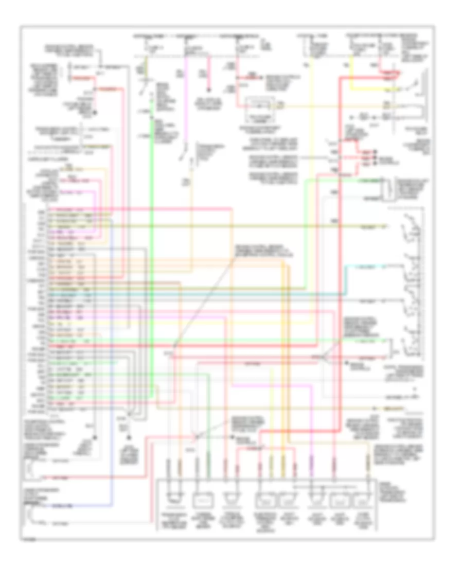
3.0L, Transmission Wiring Diagram, 4R44E for Ford Ranger 1997
List of elements for 3.0L, Transmission Wiring Diagram, 4R44E for Ford Ranger 1997:
- (dash panel to headlamp junction harness, near breakout to left headlamp)
- (engine control sensor extension harness, near breakout to harness in-line connector, left rear of engine)
- (engine control sensor harn, near breakout to in-line conn, at left rear of engine)
- (engine control sensor harness, near breakout to diff press feedback sensor)
- (engine control sensor harness, near breakout to evr solenoid)
- (engine control sensor harness, near breakout to in-line connector, at left rear of engine)
- (engine control sensor harness, near breakout to octane adjust shorting bar)
- (left side of upper radiator support) g108
- (power for heated oxygen sensors)
- (right side of firewall) g123
- (top center of left fender apron) g104
- 4r44e automatic transmission (left side of transmission)
- Boo
- Brake on/off (boo) switch (on brake pedal support)
- C111
- C214
- C216
- Case gnd
- Ccs
- Coast clutch solenoid (css)
- Cse gnd
- Digital transmission range sensor (left side of trans)
- Dlc
- Dlc (+)
- Dlc (-)
- Drl module, backup lamps, dtr sensor
- Ect
- Electronic pressure control (epc) solenoid
- Engine compartment fuse/relay box
- Engine controls
- Engine controls (ignition coil, radio noise capacitor)
- Engine coolant temperature (ect) sensor (top front of engine)
- Epc
- Fuse 13 15a
- Fuse 19 25a
- Fuse 26 10a
- G108 (left side of radiator support)
- Ho2s fuse 3 15a
- Hot at all times
- Hot in run
- Hot in start or run
- I/p fuse panel
- Instrument cluster
- Kapwr
- Malfunction indicator lamp (mil)
- Memory power fuse 5 15a
- Mil
- O/d off
- Pcm power diode
- Pcm power fuse 2 30a
- Pcm power relay
- Power
- Powertrain control module (pcm) (right rear of engine compartment, through firewall)
- Pwr gnd
- R p
- Red
- S100 (engine control sensor harness, near breakout to intake air temp sensor)
- S1002
- S102
- S103
- S104
- S106
- S110
- S111
- S112
- S113
- S121
- S147
- S228 (main harn, near breakout to instrument cluster)
- Shift solenoid (ss1)
- Shift solenoid (ss2)
- Shift solenoid (ss3)
- Sig rtn
- Ss1
- Ss2
- Ss3
- Tcc
- Tcil
- Tcs
- Tft
- Throttle position (tp) sensor (top right side of engine, on throttle body)
- Torque converter clutch (tcc) solenoid
- Tr1
- Tr2
- Tr4
- Transmission control indicator lamp (tcil)
- Transmission control switch (tcs)
- Transmission fluid temperature (tft) sensor
- Tss
- Turbine shaft speed (tss) sensor
- Vehicle speed sensor (vss) (left rear of transmission) (4x2 models) (left rear of transfer case) (4x4 models)
- Vref
- Vss
Transfer Case Wiring Diagram for Ford Ranger 1997
List of elements for Transfer Case Wiring Diagram for Ford Ranger 1997:
- (behind dash, right side of steering column) relay box 1
- (main harness, in breakout to generic electronic module (gem) connectors)
- (main harness, near breakout to dash fuse panel)
- (top center of left fender apron) g104
- 1.1k ohms
- 3.9k ohms
- 4 wheel drive fuse 4 20a
- 4wd hi ind
- 4wd ind ctrl
- 4wd lo ind
- 4wd mode sw
- 4wd mode switch
- 4wd motor
- 4wd output
- Battery saver relay
- Boo sw input
- Brake on/off (boo) switch (on brake pedal support)
- C214
- C221
- C223
- C224
- Ccw relay
- Ccw rly ctrl
- Clutch
- Cw relay
- Cw rly ctrl
- Digital transmission range (dtr) sensor (left side of transmission)
- Elc rly ctrl
- Electric clutch relay
- Electric shift control module (behind center of dash)
- Engine compartment fuse/relay box
- Fuse 13 15a
- Fuse 27 15a
- Fuse 3 in i/p fuse panel (feed to park lamps relay)
- G104 (top center of left fender apron)
- Generic electronic module (gem) (behind center of dash)
- Hot at all times
- I/p fuse panel
- Illumination
- Instrument cluster
- Interior lights
- Interior lights system (instrument illum- ination circuit)
- Nca
- Neutral sw in
- Of firewall) g123
- Ohms
- Park lamps fuse 8 20a
- Pnk
- Relay box 1 (behind dash, right side of steering column)
- Rly ctrl
- S107
- S111 (engine control sensor harness, near breakout to fuel injector 6)
- S209
- S215
- S216
- S218
- S221
- S224
- S228 (main harness, near breakout to instrument cluster connectors)
- S237
- Sig return
- Sw a input
- Sw b input
- Sw c input
- Sw d input
- Touch drive
- Transfer case assembly (below vehicle, behind transmission)
- Vehicle speed sensor (vss) (4x4 models - left rear of transfer case) (4x2 models - left rear of trans)
- Vss
- Wiper/washer (multi-function switch)
4.0L
4.0L, Transmission Wiring Diagram, 5R55E for Ford Ranger 1997
List of elements for 4.0L, Transmission Wiring Diagram, 5R55E for Ford Ranger 1997:
- (dash panel to headlamp junction harness, near breakout to left headlamp)
- (engine control sensor extension harness, near breakout to harness in-line connector, left rear of engine)
- (engine control sensor harness, near breakout to diff press feedback sensor)
- (engine control sensor harness, near breakout to fuel inj 6)
- (engine control sensor harness, near breakout to fuel injector 5)
- (engine control sensor harness, near breakout to fuel injector 6)
- (engine control sensor harness, near breakout to mass air flow sensor)
- (engine control sensor harness, near breakout to powertrain control module)
- (near dtr sensor) output shaft speed sensor
- (near dtr sensor) overdrive drum speed sensor
- (power for heated oxygen sensors)
- (top center of left fender apron) g104
- 5r55e automatic transmission (left side of transmission)
- Boo
- Brake on/off (boo) switch (on brake pedal support)
- C111
- C214
- C216
- Case gnd
- Ccs
- Coast clutch solenoid (css)
- Cse gnd
- Digital transmission range sensor (left side of trans)
- Dlc
- Dlc (+)
- Dlc (-)
- Drl module, backup lamps, dtr sensor
- Ect
- Electronic pressure control (epc) solenoid
- Engine compartment fuse/relay box
- Engine compartment fuse/relay box (left rear of eng compt)
- Engine controls
- Engine controls (ignition coil, radio noise capacitor)
- Engine coolant temperature (ect) sensor (top front of engine)
- Epc
- Fuse 13 15a
- Fuse 19 25a
- Fuse 26 10a
- G108 (left side of radiator support)
- G108 (left side of upper radiator support)
- G123 (right side of firewall)
- Ho2s fuse 3 15a
- Hot at all times
- Hot in run
- Hot in start or run
- I/p fuse panel
- Instrument cluster
- Kapwr
- Malfunction indicator lamp (mil)
- Memory power fuse 5 15a
- Mil
- O/d off
- Ods
- Oss
- Pcm power diode
- Pcm power fuse 2 30a
- Pcm power relay
- Power
- Powertrain control module (pcm) (right rear of engine compartment, through firewall)
- Pwr gnd
- R p
- Red
- S100 (engine control sensor harness, near breakout to intake air temp sensor)
- S1002
- S102
- S103
- S104
- S106
- S110
- S111
- S112
- S113
- S121
- S147
- S228 (main harn, near breakout to instrument cluster)
- Shift solenoid (ss1)
- Shift solenoid (ss2)
- Shift solenoid (ss3)
- Sig rtn
- Ss1
- Ss2
- Ss3
- Tcc
- Tcil
- Tcs
- Tft
- Throttle position (tp) sensor (top right side of engine, on throttle body)
- Torque converter clutch (tcc) solenoid
- Tr1
- Tr2
- Tr4
- Transmission control indicator lamp (tcil)
- Transmission control switch (tcs)
- Transmission fluid temperature (tft) sensor
- Tss
- Turbine shaft speed (tss) sensor
- Vehicle speed sensor (vss) (left rear of transmission) (4x2 models) (left rear of transfer case) (4x4 models)
- Vref
- Vss
Transfer Case Wiring Diagram for Ford Ranger 1997
List of elements for Transfer Case Wiring Diagram for Ford Ranger 1997:
- (behind dash, right side of steering column) relay box 1
- (main harness, in breakout to generic electronic module (gem) connectors)
- (main harness, near breakout to dash fuse panel)
- (top center of left fender apron) g104
- 1.1k ohms
- 3.9k ohms
- 4 wheel drive fuse 4 20a
- 4wd hi ind
- 4wd ind ctrl
- 4wd lo ind
- 4wd mode sw
- 4wd mode switch
- 4wd motor
- 4wd output
- Battery saver relay
- Boo sw input
- Brake on/off (boo) switch (on brake pedal support)
- C214
- C221
- C223
- C224
- Ccw relay
- Ccw rly ctrl
- Clutch
- Cw relay
- Cw rly ctrl
- Digital transmission range (dtr) sensor (left side of transmission)
- Elc rly ctrl
- Electric clutch relay
- Electric shift control module (behind center of dash)
- Engine compartment fuse/relay box
- Fuse 13 15a
- Fuse 27 15a
- Fuse 3 in i/p fuse panel (feed to park lamps relay)
- G104 (top center of left fender apron)
- Generic electronic module (gem) (behind center of dash)
- Hot at all times
- I/p fuse panel
- Illumination
- Instrument cluster
- Interior lights
- Interior lights system (instrument illum- ination circuit)
- Nca
- Neutral sw in
- Of firewall) g123
- Ohms
- Park lamps fuse 8 20a
- Pnk
- Relay box 1 (behind dash, right side of steering column)
- Rly ctrl
- S107
- S111 (engine control sensor harness, near breakout to fuel injector 6)
- S209
- S215
- S216
- S218
- S221
- S224
- S228 (main harness, near breakout to instrument cluster connectors)
- S237
- Sig return
- Sw a input
- Sw b input
- Sw c input
- Sw d input
- Touch drive
- Transfer case assembly (below vehicle, behind transmission)
- Vehicle speed sensor (vss) (4x4 models - left rear of transfer case) (4x2 models - left rear of trans)
- Vss
- Wiper/washer (multi-function switch)