SHIFT INTERLOCK
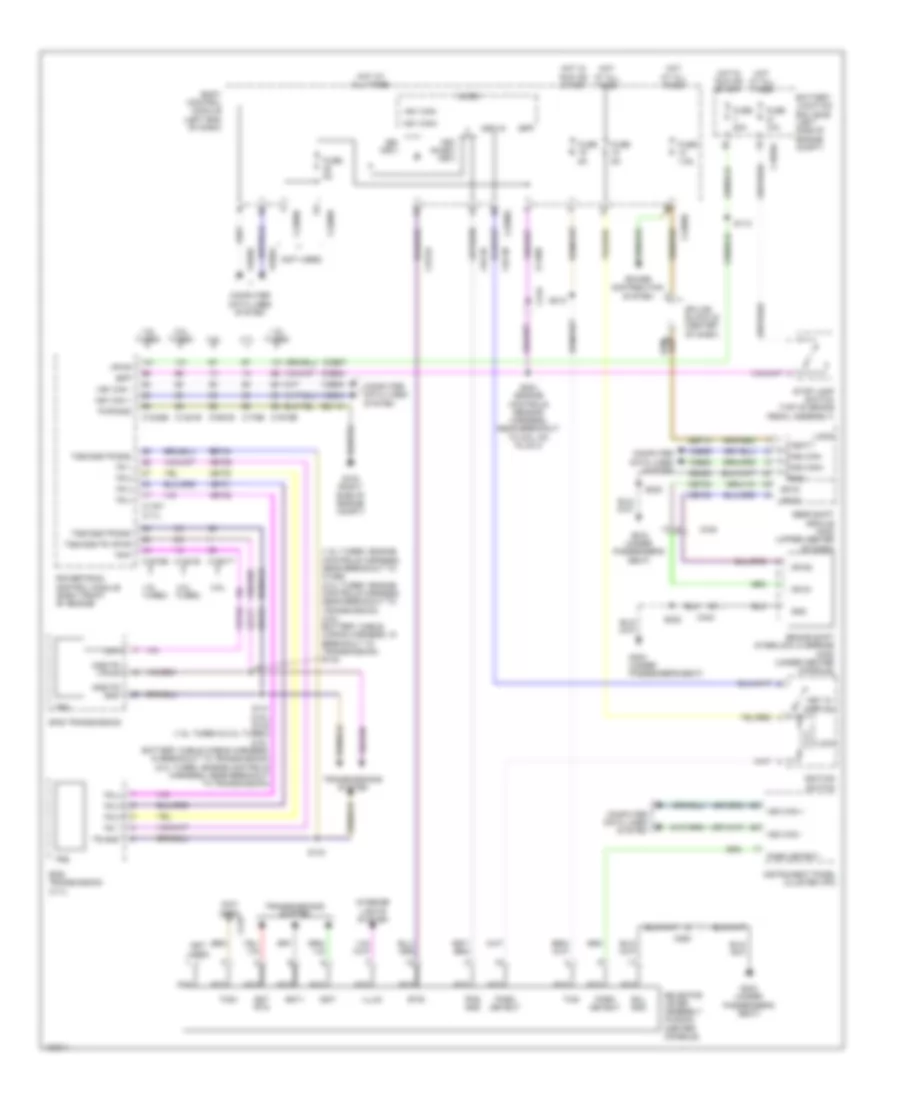
Shift Interlock Wiring Diagram, Except Hybrid for Ford Fusion SE 2014
List of elements for Shift Interlock Wiring Diagram, Except Hybrid for Ford Fusion SE 2014:
- (1.5l turbo: engine controls harness, near breakout to c1386) (2.0l turbo: engine controls harness, near breakout to transmission) (2.5l: battery cable wiring harness, in breakout to transmission) s142
- (3.7l)
- (not used)
- 1.5l turbo
- 1.6l turbo
- 2.0l
- 2.0l turbo
- 2.5l
- 3.7l
- 6f35 transmission
- 6f50 transmission (3.7l)
- Battery junction box (bjb) (left side of engine compt)
- Body control module (left end of dash)
- Bpp
- Brake shift interlock override (mkz) (under center console)
- Bsi (fet)
- Btsi
- C1035a
- C1232b
- C1381b
- C1381e
- C1551b
- C1551t
- C175b
- C175t
- C1915b
- C1915e
- C219
- C2280b
- C2280g
- C2280h
- C263
- C340
- Ccb07
- Ccb08
- Cdc26
- Cdc30
- Cet53
- Cet82
- Cet83
- Computer data lines system
- Fuse 10a
- Fuse 20a
- Fuse 5a
- Fuse 7.5a
- G104 (right side of engine compt)
- G303 (under passenger's seat)
- Gd113
- Gd383
- Gear shift module (mkz) (upper center of dash)
- Gnd
- Hot at all times
- Hot in run or start
- Hs1 can +
- Hs1 can -
- Hs1 can+
- Hs1 can-
- Hs2 can+
- Hs2 can-
- Hs3 can +
- Hs3 can -
- Ignition switch
- Illum
- Instrument panel cluster (ipc)
- Interior lights system
- Key in
- Key in ignition
- Key inhibit (fet)
- Le111
- Lock
- Logic
- Micro
- Nca
- Or s1
- Or s2
- Oss/tr gnd
- Oss/tr vpwr
- Park detect
- Pds gnd
- Power distribution system
- Powertrain control module (right front of engine)
- Pwr gnd
- Ret24
- S112
- S141 (2.5l) s143 (1.5l turbo & 2.0l turbo) (2.5l: battery cable wiring harness, in breakout to transmission) (2.0l turbo :engine controls harness, near breakout to transmission)
- S143
- S204 (engine controls sensor harness, near breakout to coil on plug 3)
- S212
- S222
- Sbp12
- Selector lever assembly (fusion) (center console)
- Sol gnd
- Splice block 22 (center of dash)
- Sst rtn
- Sst+
- Sst-
- Stop lamp switch (top of brake pedal assembly)
- Tcs+
- Tcs-
- Tr 1
- Tr 2
- Tr 3
- Tr 4
- Tr gnd
- Tr-p
- Transmissions system
- Trs
- Tss/oss/tr gnd
- Tss/oss/tr vpwr
- Turbo
- Vbatt
- Vdb04
- Vdb05
- Vdb25
- Vdb26
- Vet29
- Vet30
- Vet31
- Vet32
- Vpwr
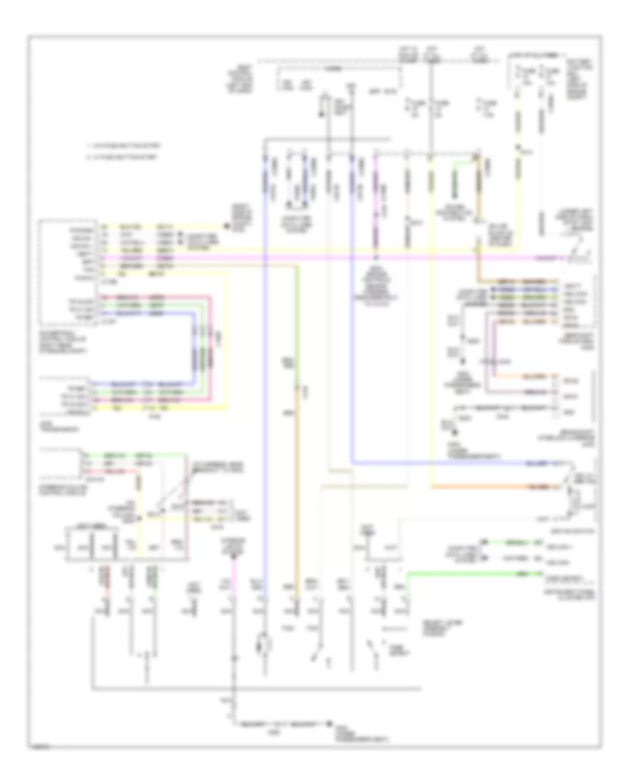
Shift Interlock Wiring Diagram, Hybrid for Ford Fusion SE 2014
List of elements for Shift Interlock Wiring Diagram, Hybrid for Ford Fusion SE 2014:
- (i/p harness, near breakout to g202)
- (not used)
- (on steering column) s205
- (right side of engine compt) g105
- (under left side of dash) stop lamp switch
- Battery junction box (left side of engine compt)
- Body control module (left end of dash)
- Bpp
- Brake shift interlock override (mkz)
- Btsi
- C1026
- C1035a
- C146
- C175b
- C175t
- C219
- C2280b
- C2280g
- C2280h
- C2414a
- C263
- C340
- Ccb08
- Cdc26
- Cdc30
- Cet34
- Cet42
- Cet43
- Cet53
- Cet82
- Cet83
- Computer data lines system
- Fuse 10a
- Fuse 5a
- Fuse 7.5a
- G303 (under passenger's seat)
- Gd113
- Gd383
- Gear shift module (gsm) (mkz)
- Gnd
- Hf35 transmission
- Hot at all times
- Hot in run or start
- Hs can +
- Hs can -
- Hs1 can+
- Hs1 can-
- Hs2 can+
- Hs2 can-
- Hs3 can +
- Hs3 can -
- Ignition switch
- Instrument panel cluster (ipc)
- Interior lights system
- Key in
- Key in ignition
- Key inhibit (fet)
- Le458
- Let56
- Let57
- Lock
- Micro
- Nca
- Or s1
- Or s2
- Park detect
- Power distribution system
- Powertrain control module (right rear of engine compt)
- Pwr gnd
- Re407
- Ret57
- S141
- S204 (engine controls sensor harness, near breakout to c1010)
- S212
- S214
- S216
- S222
- Sbb18
- Sbp12
- Select lever assembly (fusion)
- Splice block 22 (center of dash)
- Steering column control module
- Tcs
- Tcs+
- Tcs-
- Tr a1 sig
- Tr a2 sig
- Tr ref
- Tr rtn
- Vbatt
- Vdb04
- Vdb05
- Vdb25
- Vdb26
- W/ push button start
- W/o push button start

 Deutsch
 English
 Español
 Français
 Nederlands
 Русский


