STARTING/CHARGING
Charging Wiring Diagram for Ford Fusion SE 2014
 https://portal-diagnostov.com/license.html
Automotive Electricians Portal FZCO
Automotive Electricians Portal FZCO
https://portal-diagnostov.com/license.html
https://portal-diagnostov.com/license.html
Automotive Electricians Portal FZCO
Automotive Electricians Portal FZCO
List of elements for Charging Wiring Diagram for Ford Fusion SE 2014:
- (engine controls sensor harness, near breakout to coil on plug 3) s126
- (engine controls sensor harness, near breakout to pcm)
- 1.5l turbo
- 1.6l turbo
- 1.6l turbo, 1.5l turbo & 2.5l
- 2.0l turbo
- 2.5l
- 3.7l
- 3.7l & 2.0l turbo
- Battery
- Battery junction box (bjb) (left side of engine compt)
- Bcs2 alt
- Body control module (bcm) (left end of dash)
- C102a
- C102c
- C1035a
- C1035c
- C1232b
- C1381b
- C146
- C1551b
- C1558a
- C1558c
- C1617a
- C1617c
- C1617e
- C1716a
- C1716c
- C1716e
- C175b
- C1915b
- C2280b
- C2280c
- Cdc10
- Cdc15
- Cdc56
- Computer data lines system
- Controls system
- Engine
- Fuse 10a
- G108 (left rear of engine compt)
- G109 (rear of engine)
- Gencom
- Generator
- Generator current sensor (on generator)
- Genmon
- High current battery junction box (bjb) (left side of engine compt)
- Hs1 can +
- Hs1 can -
- Hs3 can +
- Hs3 can -
- Instrument panel cluster (ipc)
- Ldc59
- Le423
- Mcro
- Mega fuse 8 275a (or 200a)
- Mon
- Nca
- Power distribution system
- Powertrain control module (pcm) (right front of engine)
- Rdc59
- Re407
- Red
- S133
- Sdc57
- Sen+
- Sen-
- Sigrtn
- Vdb04
- Vdb05
- Vdc61
- Vref
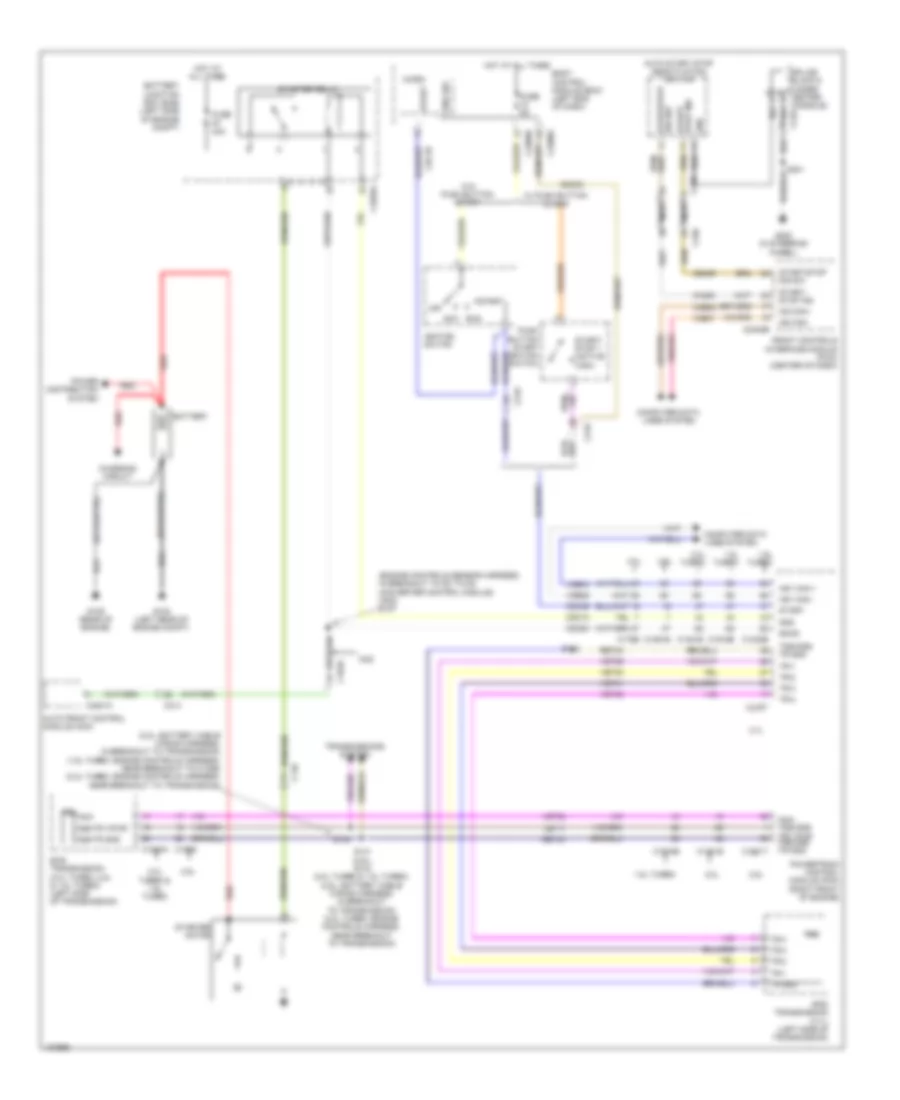
Starting Wiring Diagram for Ford Fusion SE 2014
List of elements for Starting Wiring Diagram for Ford Fusion SE 2014:
- (2.5l: battery cable wiring harness, in breakout to transmission) (1.5l turbo: engine controls harness, near breakout to c1386) (2.ol turbo: engine controls harness, near breakout to transmission)
- (engine controls sensor harness, in breakout to dc to dc converter control module) (mkz) s157
- 1.5l turbo
- 1.6l turbo
- 2.0l
- 2.0l turbo
- 2.0l turbo & 1.5l turbo
- 2.5l
- 3.7l
- 6f35 transmission (2.0l turbo, 2.5l & 1.5l turbo) (left side of transmission)
- 6f50 transmission (3.7l) (left side of transmission)
- Acc
- Auto front control module (acm)
- Auto start stop deactivation switch
- Battery
- Battery junction box (bjb) (left side of engine compt)
- Body control module (bcm) (left end of dash)
- C1010
- C1035a
- C1232b
- C1381b
- C1381e
- C146
- C1520a
- C1551b
- C1551t
- C175b
- C175t
- C1909
- C1915b
- C1915e
- C210
- C214
- C219
- C2280g
- C2280h
- C2402b
- C340
- C4821a
- Cdc12
- Cdc35
- Cdc54
- Ce469
- Ch253
- Charging circuit
- Computer data lines system
- Eng sw
- Front controls interface module (fcim) (center of dash)
- Fuse 30a
- Fuse 5a
- G108 (left rear of engine compt)
- G109 (rear of engine)
- G200 (in steering wheel)
- Gnd
- Hot at all times
- Hs1 can +
- Hs1 can -
- Ignition switch
- Le111
- Micro
- Mkz
- Ms can+
- Ms can-
- Nca
- Off
- Oss/tr gnd
- Oss/tr vpwr
- Power distribution system
- Powertrain control module (pcm) (right front of engine)
- Push button start ignition switch
- Red
- Ret24
- Run
- S141 (2.5l) s143 (2.0l turbo & 1.5l turbo) (2.5l: battery cable wiring harness, in breakout to transmission) (2.0l turbo: engine controls harness, near breakout to transmission)
- S142
- S143
- S301
- Smcs
- Splice block 6 (under center console)
- Start
- Start/ stop 1 (active high)
- Start/ stop ind
- Start/stop dis sw
- Starter motor
- Starter relay
- Stop ind start/
- Tr gnd
- Tr-1
- Tr-2
- Tr-3
- Tr-4
- Tr-p
- Tr-p tss/oss/ trv pwr tss/oss /tr gnd
- Transmissions system
- Trs
- Tss/oss/ tr gnd
- Vdb04
- Vdb05
- Vdb06
- Vdb07
- Vet29
- Vet30
- Vet31
- Vet32
- W/ push button start
- W/o push button start


 Deutsch
 English
 Español
 Français
 Nederlands
 Русский

