AIR CONDITIONING
3.8L VIN 2
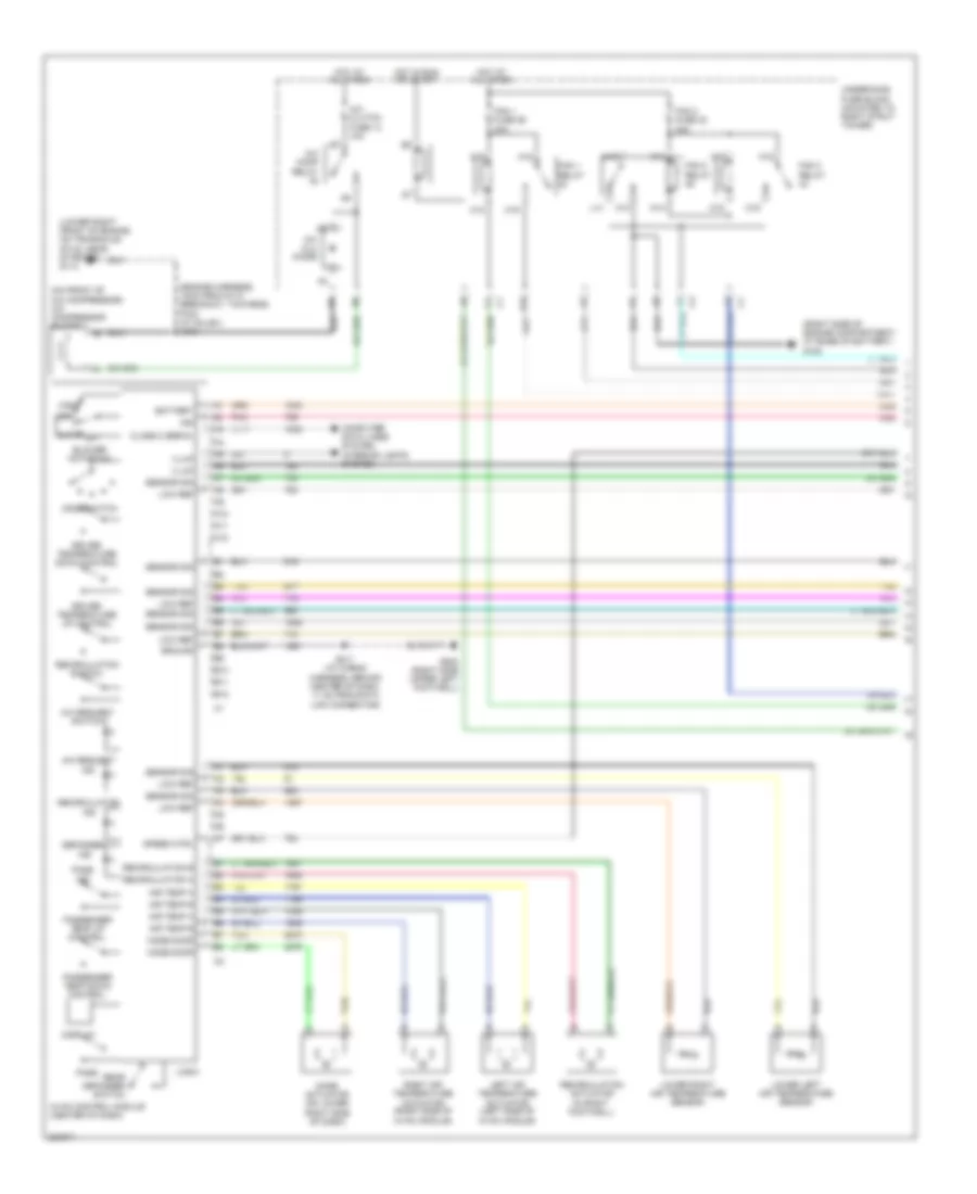
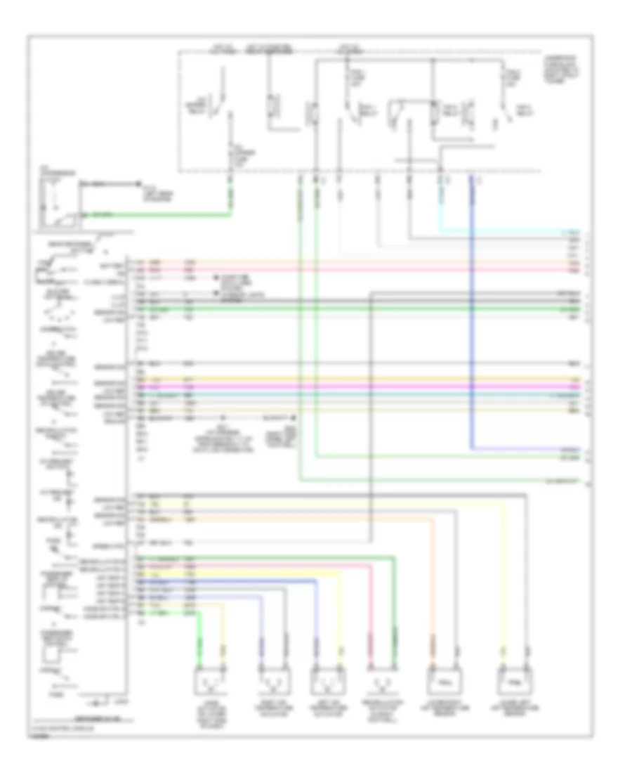
3.8L VIN 2, Automatic A/C Wiring Diagram (1 of 2) for Pontiac Grand Prix GTP 2005

List of elements for 3.8L VIN 2, Automatic A/C Wiring Diagram (1 of 2) for Pontiac Grand Prix GTP 2005:
- (engine harness, 10cm from g113 breakout, towards pcm) (w/ sulev) s104
- (lower right front of engine, on transaxle stud, near starter) g113
- (on front of a/c compressor) a/c compressor clutch
- (right side of engine compartment, at base of battery) g100
- A/c clu diode
- A/c clutch fuse 13 10a
- A/c comp relay
- A/c request ind
- A/c request switch
- A10
- A11
- A12
- A18
- A19
- Air temp a
- Air temp b
- Auto
- B10
- B11
- B12
- Battery
- Blower motor sw
- C18
- C19
- Class 2 serial
- Computer data lines system interior lights system
- Defogger
- Display
- Driver temperature down control
- Driver temperature up control
- E10
- Fan 1 fuse 29 30a
- Fan 1 relay
- Fan 2 fuse 32 30a
- Fan 2 relay
- Fan 3 relay
- G202 (right side upper left footwell)
- Ground
- High
- Hot at all times
- Hot in run or start
- Hvac control module (center of dash)
- Ign
- Illum
- Ind
- K14
- K15
- K18
- K19
- L14
- Left air temperature actuator (left side of hvac module)
- Logic
- Low
- Low ref
- Lower left air temperature sensor
- Lower right air temperature sensor
- M14
- M15
- M18
- M19
- Mode actuator (on lower right side of dash)
- Mode door
- Mode switch
- Off
- Pass
- Passenger temp down control
- Passenger temp up control
- Pnk
- Rear defogger switch
- Recirculation
- Recirculation a
- Recirculation actuator (in right footwell)
- Recirculation b
- Recirculation switch
- Right air temperature actuator (right side of hvac module)
- S211 (i/p wiring harness, behind center of dash, 11 cm from data link connector)
- Sensor sig
- Speed ctrl
- Tan
- Underhood fuse block (mounted to right strut tower)
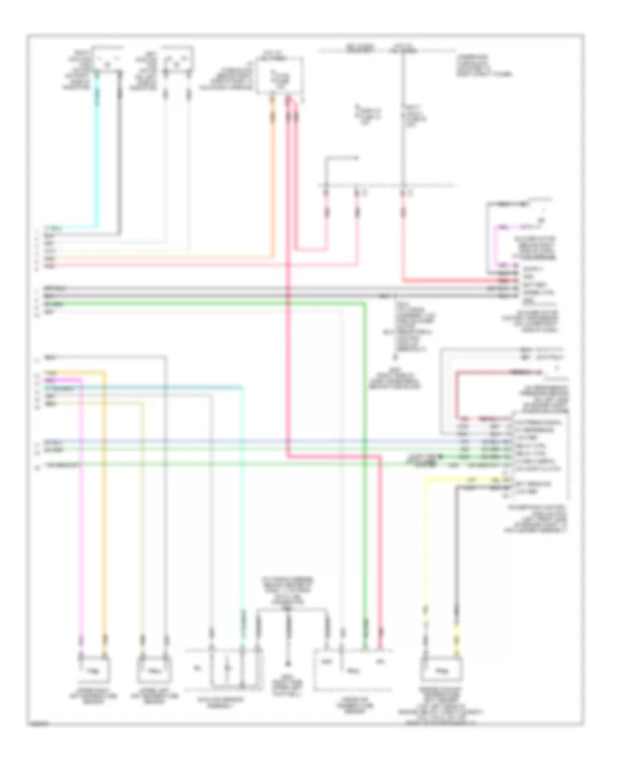
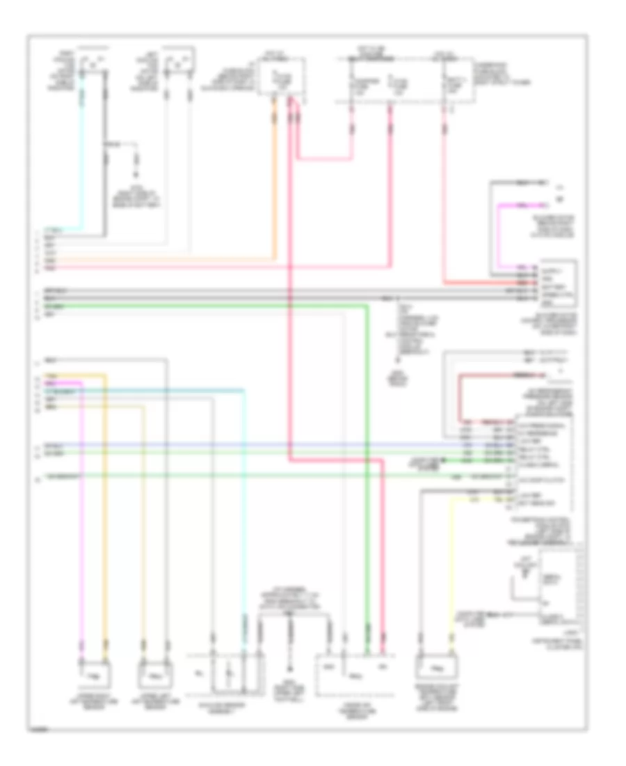
3.8L VIN 2, Automatic A/C Wiring Diagram (2 of 2) for Pontiac Grand Prix GTP 2005
List of elements for 3.8L VIN 2, Automatic A/C Wiring Diagram (2 of 2) for Pontiac Grand Prix GTP 2005:
- (i/p wiring harness, behind center of dash, 11 cm from data link connector) s211
- 5v reference
- A/c comp clutch
- A/c press signal
- A/c refrigerant pressure sensor (on left side of engine compt, on accumulator)
- Batt main 4 fuse 30 30a
- Battery
- Blower motor (behind right side of dash, in hvac module)
- Blower motor control processor (on lower right side of dash)
- Class 2 serial
- Computer data lines system
- D11
- Display fuse 18 10a
- Ect sens sig
- Engine coolant temperature (ect) sensor (top left rear of engine, below throttle body) (3.8l (vin 2): on top right of intake manifold)
- G200 (right side of dash cross beam, behind fuse block)
- G202 (right side upper left footwell)
- Gnd
- Hot at all times
- Hot in run or start
- Hvac fuse 10a
- I/p fuse block (behind right side of dash, in glove box opening)
- Ign
- Inside air temperature sensor
- Left cooling fan motor (on left side of radiator)
- Low ref
- Pnk
- Powertrain control module (pcm) (left front side of engine compt, in air cleaner assembly)
- Red
- Relay ctrl
- Right cooling fan motor (on right b
- S213 (i/p wiring harness, 4 cm from blower motor resistors & control module breakout)
- Speed ctrl
- Sunload sensor assembly
- Tan
- Underhood fuse block (mounted to right strut tower)
- Upper left air temperature sensor
- Upper right air temperature sensor
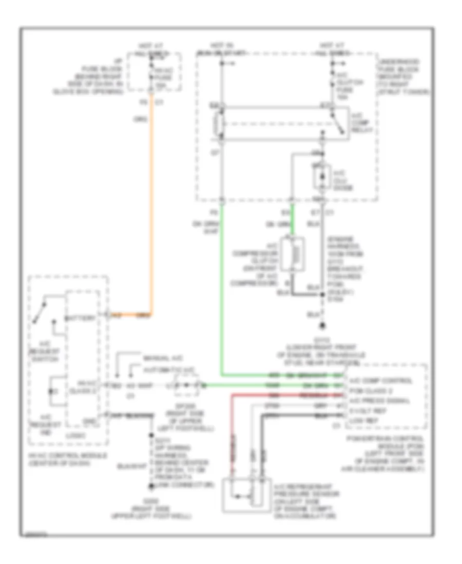
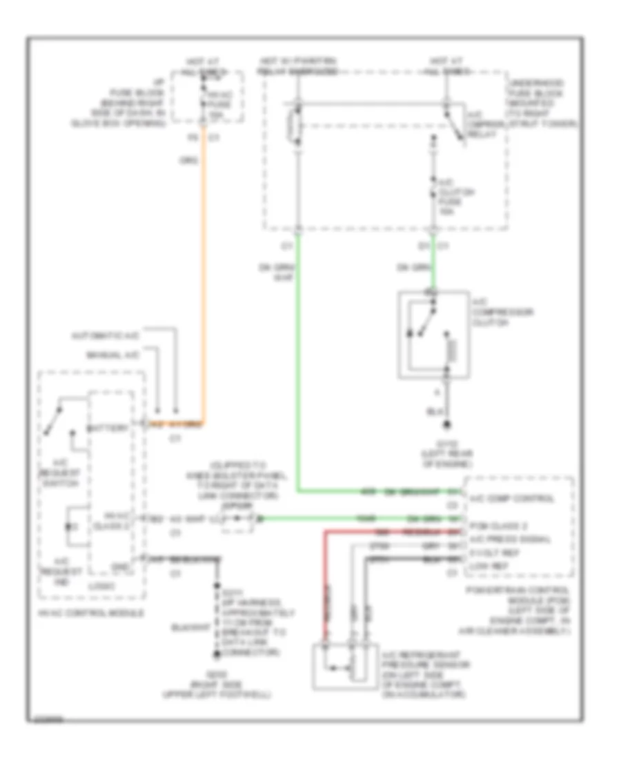
3.8L VIN 2, Compressor Wiring Diagram for Pontiac Grand Prix GTP 2005
List of elements for 3.8L VIN 2, Compressor Wiring Diagram for Pontiac Grand Prix GTP 2005:
- (engine harness, 10cm from g113 breakout, towards pcm) (sulev) s104
- 5 volt ref
- A/c clu diode
- A/c clutch fuse 10a
- A/c comp control
- A/c comp relay
- A/c compressor clutch (on front of a/c compressor) b
- A/c press signal
- A/c refrigerant pressure sensor (on left side of engine compt, on accumulator)
- A/c request ind
- A/c request switch
- Automatic a/c
- Battery
- G113 (lower right front of engine, on transaxle stud, near starter)
- G202 (right side upper left footwell)
- Gnd
- Hot at all times
- Hot in run or start
- Hvac class 2
- Hvac control module (center of dash)
- Hvac fuse 10a
- I/p fuse block (behind right side of dash, in glove box opening)
- Logic
- Low ref
- Manual a/c
- Pcm class 2
- Powertrain control module (pcm) (left front side of engine compt, in air cleaner assembly)
- S211 (i/p wiring harness, behind center of dash, 11 cm from data link connector)
- Sp205 (right side of upper left footwell)
- Underhood fuse block (mounted to right strut tower)
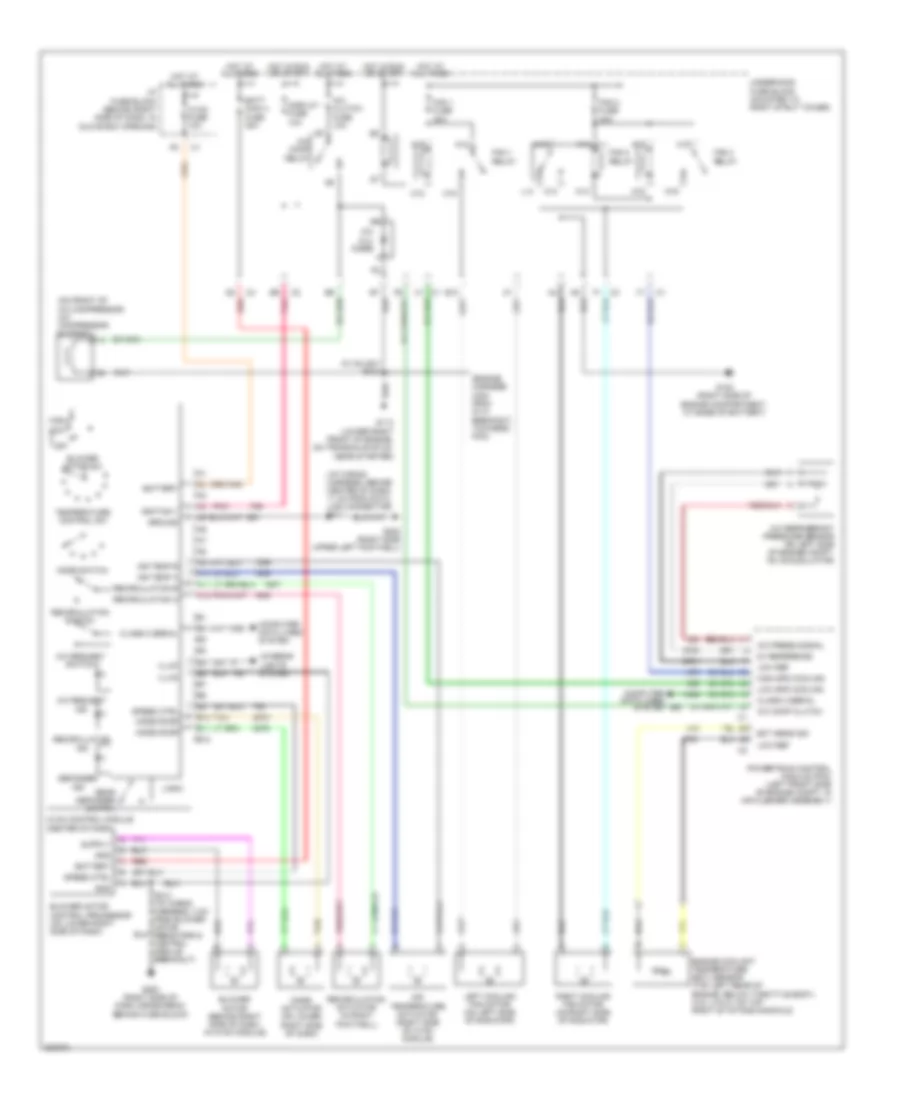
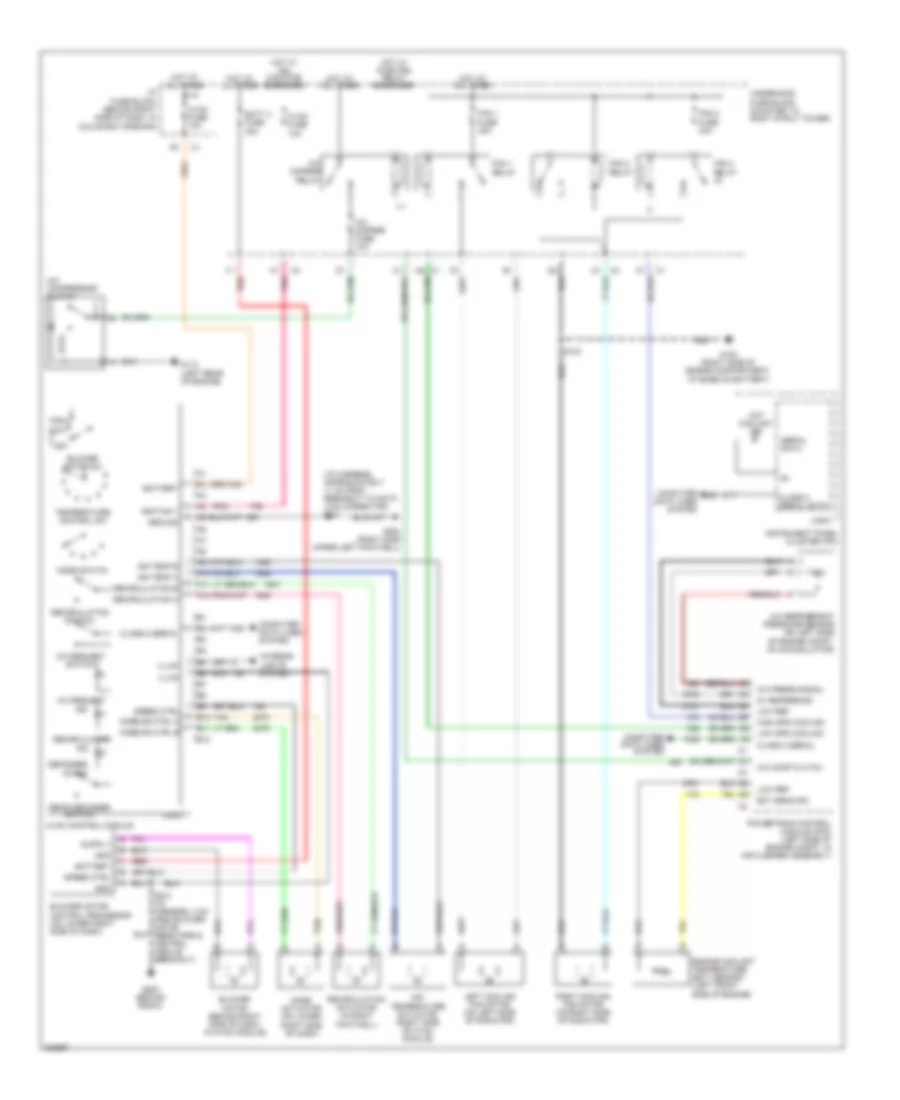
3.8L VIN 2, Manual A/C Wiring Diagram for Pontiac Grand Prix GTP 2005
List of elements for 3.8L VIN 2, Manual A/C Wiring Diagram for Pontiac Grand Prix GTP 2005:
- (engine harness, 10cm from g113 breakout, towards pcm)
- (i/p wiring harness, behind center of dash, 11 cm from data link connector) s211
- (on front of a/c compressor) a/c compressor clutch
- (w/ sulev) s104
- 5v reference
- A/c clu diode
- A/c clutch fuse 10a
- A/c comp clutch
- A/c comp relay
- A/c press signal
- A/c refrigerant pressure sensor (on left side of engine compt, on accumulator)
- A/c request ind
- A/c request switch
- A10
- A11
- A12
- A18
- A19
- Air temp a
- Air temp b
- Air temperature actuator (right side of hvac module)
- B10
- B11
- B12
- Batt main 4 fuse 30a
- Battery
- Blower motor (behind right side of dash, in hvac module)
- Blower motor control processor (on lower right side of dash)
- Blower motor sw
- C18
- C19
- Class 2 serial
- Computer data lines system
- Defogger
- Display fuse 10a
- E10
- Ect sens sig
- Engine coolant temperature (ect) sensor (top left rear of engine, below throttle body) (3.8l (vin 2): on top right of intake manifold)
- Fan 1 fuse 30a
- Fan 1 relay
- Fan 2 fuse 30a
- Fan 2 relay
- Fan 3 relay
- G100 (right side of engine compartment, at base of battery)
- G113 (lower right front of engine, on transaxle stud, near starter)
- G200 (right side of dash cross beam, behind fuse block)
- G202 (right side upper left footwell)
- Gnd
- Ground
- High
- High spd cooling
- Hot at all times
- Hot in run or start
- Hvac control module (center of dash)
- Hvac fuse 10a
- I/p fuse block (behind right side of dash, in glove box opening)
- Ignition 1
- Illum
- Ind
- Interior lights system
- K14
- K15
- K18
- K19
- L14
- Left cooling fan motor (on left side of radiator)
- Logic
- Low
- Low ref
- Low spd cooling
- M14
- M15
- M18
- M19
- Mode actuator (on lower right side of dash)
- Mode door
- Mode switch
- Off
- Pnk
- Powertrain control module (pcm) (left front side of engine compt, in air cleaner assembly)
- Rear defogger switch
- Recirculation
- Recirculation a
- Recirculation actuator (in right footwell)
- Recirculation b
- Recirculation switch
- Red
- Right cooling fan motor (on right side of radiator)
- S213 (i/p wiring harness, 4 cm from blower motor resistors & control module breakout)
- Speed ctrl
- Tan
- Temperature control sw
- Underhood fuse block (mounted to right strut tower)
3.8L VIN 4
3.8L VIN 4, Automatic A/C Wiring Diagram (1 of 2) for Pontiac Grand Prix GTP 2005
List of elements for 3.8L VIN 4, Automatic A/C Wiring Diagram (1 of 2) for Pontiac Grand Prix GTP 2005:
- (engine harness, 10cm from g113 breakout, towards pcm) (w/ sulev) s104
- (lower right front of engine, on transaxle stud, near starter) g113
- (on front of a/c compressor) a/c compressor clutch
- (right side of engine compartment, at base of battery) g100
- A/c clu diode
- A/c clutch fuse 13 10a
- A/c comp relay
- A/c request ind
- A/c request switch
- A10
- A11
- A12
- A18
- A19
- Air temp a
- Air temp b
- Auto
- B10
- B11
- B12
- Battery
- Blower motor sw
- C18
- C19
- Class 2 serial
- Computer data lines system interior lights system
- Defogger
- Display
- Driver temperature down control
- Driver temperature up control
- E10
- Fan 1 fuse 29 30a
- Fan 1 relay
- Fan 2 fuse 32 30a
- Fan 2 relay
- Fan 3 relay
- G202 (right side upper left footwell)
- Ground
- High
- Hot at all times
- Hot in run or start
- Hvac control module (center of dash)
- Ign
- Illum
- Ind
- K14
- K15
- K18
- K19
- L14
- Left air temperature actuator (left side of hvac module)
- Logic
- Low
- Low ref
- Lower left air temperature sensor
- Lower right air temperature sensor
- M14
- M15
- M18
- M19
- Mode actuator (on lower right side of dash)
- Mode door
- Mode switch
- Off
- Pass
- Passenger temp down control
- Passenger temp up control
- Pnk
- Rear defogger switch
- Recirculation
- Recirculation a
- Recirculation actuator (in right footwell)
- Recirculation b
- Recirculation switch
- Right air temperature actuator (right side of hvac module)
- S211 (i/p wiring harness, behind center of dash, 11 cm from data link connector)
- Sensor sig
- Speed ctrl
- Tan
- Underhood fuse block (mounted to right strut tower)
3.8L VIN 4, Automatic A/C Wiring Diagram (2 of 2) for Pontiac Grand Prix GTP 2005
List of elements for 3.8L VIN 4, Automatic A/C Wiring Diagram (2 of 2) for Pontiac Grand Prix GTP 2005:
- (i/p wiring harness, behind center of dash, 11 cm from data link connector) s211
- 5v reference
- A/c comp clutch
- A/c press signal
- A/c refrigerant pressure sensor (on left side of engine compt, on accumulator)
- Batt main 4 fuse 30 30a
- Battery
- Blower motor (behind right side of dash, in hvac module)
- Blower motor control processor (on lower right side of dash)
- Class 2 serial
- Computer data lines system
- D11
- Display fuse 18 10a
- Ect sens sig
- Engine coolant temperature (ect) sensor (top left rear of engine, below throttle body) (3.8l (vin 2): on top right of intake manifold)
- G200 (right side of dash cross beam, behind fuse block)
- G202 (right side upper left footwell)
- Gnd
- Hot at all times
- Hot in run or start
- Hvac fuse 10a
- I/p fuse block (behind right side of dash, in glove box opening)
- Ign
- Inside air temperature sensor
- Left cooling fan motor (on left side of radiator)
- Low ref
- Pnk
- Powertrain control module (pcm) (left front side of engine compt, in air cleaner assembly)
- Red
- Relay ctrl
- Right cooling fan motor (on right b
- S213 (i/p wiring harness, 4 cm from blower motor resistors & control module breakout)
- Speed ctrl
- Sunload sensor assembly
- Tan
- Underhood fuse block (mounted to right strut tower)
- Upper left air temperature sensor
- Upper right air temperature sensor
3.8L VIN 4, Compressor Wiring Diagram for Pontiac Grand Prix GTP 2005
List of elements for 3.8L VIN 4, Compressor Wiring Diagram for Pontiac Grand Prix GTP 2005:
- (engine harness, 10cm from g113 breakout, towards pcm) (sulev) s104
- 5 volt ref
- A/c clu diode
- A/c clutch fuse 10a
- A/c comp control
- A/c comp relay
- A/c compressor clutch (on front of a/c compressor) b
- A/c press signal
- A/c refrigerant pressure sensor (on left side of engine compt, on accumulator)
- A/c request ind
- A/c request switch
- Automatic a/c
- Battery
- G113 (lower right front of engine, on transaxle stud, near starter)
- G202 (right side upper left footwell)
- Gnd
- Hot at all times
- Hot in run or start
- Hvac class 2
- Hvac control module (center of dash)
- Hvac fuse 10a
- I/p fuse block (behind right side of dash, in glove box opening)
- Logic
- Low ref
- Manual a/c
- Pcm class 2
- Powertrain control module (pcm) (left front side of engine compt, in air cleaner assembly)
- S211 (i/p wiring harness, behind center of dash, 11 cm from data link connector)
- Sp205 (right side of upper left footwell)
- Underhood fuse block (mounted to right strut tower)
3.8L VIN 4, Manual A/C Wiring Diagram for Pontiac Grand Prix GTP 2005
List of elements for 3.8L VIN 4, Manual A/C Wiring Diagram for Pontiac Grand Prix GTP 2005:
- (engine harness, 10cm from g113 breakout, towards pcm)
- (i/p wiring harness, behind center of dash, 11 cm from data link connector) s211
- (on front of a/c compressor) a/c compressor clutch
- (w/ sulev) s104
- 5v reference
- A/c clu diode
- A/c clutch fuse 10a
- A/c comp clutch
- A/c comp relay
- A/c press signal
- A/c refrigerant pressure sensor (on left side of engine compt, on accumulator)
- A/c request ind
- A/c request switch
- A10
- A11
- A12
- A18
- A19
- Air temp a
- Air temp b
- Air temperature actuator (right side of hvac module)
- B10
- B11
- B12
- Batt main 4 fuse 30a
- Battery
- Blower motor (behind right side of dash, in hvac module)
- Blower motor control processor (on lower right side of dash)
- Blower motor sw
- C18
- C19
- Class 2 serial
- Computer data lines system
- Defogger
- Display fuse 10a
- E10
- Ect sens sig
- Engine coolant temperature (ect) sensor (top left rear of engine, below throttle body) (3.8l (vin 2): on top right of intake manifold)
- Fan 1 fuse 30a
- Fan 1 relay
- Fan 2 fuse 30a
- Fan 2 relay
- Fan 3 relay
- G100 (right side of engine compartment, at base of battery)
- G113 (lower right front of engine, on transaxle stud, near starter)
- G200 (right side of dash cross beam, behind fuse block)
- G202 (right side upper left footwell)
- Gnd
- Ground
- High
- High spd cooling
- Hot at all times
- Hot in run or start
- Hvac control module (center of dash)
- Hvac fuse 10a
- I/p fuse block (behind right side of dash, in glove box opening)
- Ignition 1
- Illum
- Ind
- Interior lights system
- K14
- K15
- K18
- K19
- L14
- Left cooling fan motor (on left side of radiator)
- Logic
- Low
- Low ref
- Low spd cooling
- M14
- M15
- M18
- M19
- Mode actuator (on lower right side of dash)
- Mode door
- Mode switch
- Off
- Pnk
- Powertrain control module (pcm) (left front side of engine compt, in air cleaner assembly)
- Rear defogger switch
- Recirculation
- Recirculation a
- Recirculation actuator (in right footwell)
- Recirculation b
- Recirculation switch
- Red
- Right cooling fan motor (on right side of radiator)
- S213 (i/p wiring harness, 4 cm from blower motor resistors & control module breakout)
- Speed ctrl
- Tan
- Temperature control sw
- Underhood fuse block (mounted to right strut tower)
5.3L VIN C
5.3L VIN C, Automatic A/C Wiring Diagram (1 of 2) for Pontiac Grand Prix GTP 2005
List of elements for 5.3L VIN C, Automatic A/C Wiring Diagram (1 of 2) for Pontiac Grand Prix GTP 2005:
- A/c compressor clutch
- A/c cmprsr fuse 10a
- A/c cmprsr relay
- A/c request ind
- A/c request switch
- A10
- A11
- A12
- Air temp a
- Air temp b
- Auto
- B10
- B11
- B12
- Battery
- Blower motor sw
- Class 2 serial
- Computer data lines system interior lights system
- Defogger on ind
- Display
- Driver temperature down control
- Driver temperature up control
- Fan 1 fuse 30a
- Fan 1 relay
- Fan 2 fuse 30a
- Fan 2 relay
- Fan 3 relay
- G112 (left rear of engine)
- G202 (right side upper left footwell)
- Ground
- High
- Hot at all times
- Hot w/ pwr/trn relay energized
- Hvac control module
- Ign
- Illum
- Ind
- Left air temperature actuator
- Logic
- Low
- Low ref
- Lower left air temperature sensor
- Lower right air temperature sensor
- Mode actuator (on lower right side of dash)
- Mode dr ctrl a
- Mode dr ctrl b
- Mode switch
- Off
- Pass
- Passenger temp down control
- Passenger temp up control
- Pnk
- Rear defogger switch
- Recirculation
- Recirculation a
- Recirculation actuator (in right footwell)
- Recirculation b
- Recirculation switch
- Right air temperature actuator
- S211 (i/p harness, approximately 11 cm from breakout to data link connector)
- Sensor sig
- Speed ctrl
- Tan
- Underhood fuse block (mounted to right strut tower)
5.3L VIN C, Automatic A/C Wiring Diagram (2 of 2) for Pontiac Grand Prix GTP 2005
List of elements for 5.3L VIN C, Automatic A/C Wiring Diagram (2 of 2) for Pontiac Grand Prix GTP 2005:
- (i/p harness, approximately 11 cm from breakout to data link connector) s211
- 5v reference
- A/c comp clutch
- A/c press signal
- A/c refrigerant pressure sensor (on left side of engine compt, on accumulator)
- Batt 4 fuse 30a
- Battery
- Blower motor (behind right side of dash, in hvac module)
- Blower motor control processor (on lower right side of dash)
- Class 2 serial
- Class 2 serial data
- Compass fuse 10a
- Computer data lines system
- D11
- Ect sens sig
- Engine coolant temperature (ect) sensor (left front side of engine)
- G100 (right side of engine compt, at base of battery)
- G200 (behind radio)
- G202 (right side upper left footwell)
- Gnd
- Hot at all times
- Hot coolant ind
- Hot w/ ign main pcb relay energized
- Hvac fuse 10a
- I/p fuse block (behind right side of dash, in glove box opening)
- Ign
- Inside air temperature sensor
- Instrument panel cluster (ipc)
- Left cooling fan motor (on left side of radiator)
- Logic
- Low ref
- Pnk
- Powertrain control module (pcm) (left side of engine compt, in air cleaner assembly)
- Red
- Relay ctrl
- Right cooling fan motor (on right b
- S123
- S213 (i/p harness, 4 cm from blower motor resistors & control module breakout)
- Serial data
- Speed ctrl
- Sunload sensor assembly
- Tan
- Underhood fuse block (mounted to right strut tower)
- Upper left air temperature sensor
- Upper right air temperature sensor
5.3L VIN C, Compressor Wiring Diagram for Pontiac Grand Prix GTP 2005
List of elements for 5.3L VIN C, Compressor Wiring Diagram for Pontiac Grand Prix GTP 2005:
- (clipped to knee-bolster panel, to right of data link connector) sp205
- 5 volt ref
- A/c compressor clutch
- A/c clutch fuse 10a
- A/c cmprsr relay
- A/c comp control
- A/c press signal
- A/c refrigerant pressure sensor (on left side of engine compt, on accumulator)
- A/c request ind
- A/c request switch
- Automatic a/c
- Battery
- G112 (left rear of engine)
- G202 (right side upper left footwell)
- Gnd
- Hot at all times
- Hot w/ pwr/trn relay energized
- Hvac class 2
- Hvac control module
- Hvac fuse 10a
- I/p fuse block (behind right side of dash, in glove box opening)
- Logic
- Low ref
- Manual a/c
- Pcm class 2
- Powertrain control module (pcm) (left side of engine compt, in air cleaner assembly)
- S211 (i/p harness, approximately 11 cm from breakout to data link connector)
- Underhood fuse block (mounted to right strut tower)
5.3L VIN C, Manual A/C Wiring Diagram for Pontiac Grand Prix GTP 2005
List of elements for 5.3L VIN C, Manual A/C Wiring Diagram for Pontiac Grand Prix GTP 2005:
- (i/p harness, approximately 11 cm from breakout to data link connector) s211
- 5v reference
- A/c compressor clutch
- A/c cmprsr fuse 10a
- A/c cmprsr relay
- A/c comp clutch
- A/c press signal
- A/c refrigerant pressure sensor (on left side of engine compt, on accumulator)
- A/c request ind
- A/c request switch
- A10
- A11
- A12
- Air temp a
- Air temp b
- Air temperature actuator (right side of hvac module)
- B10
- B11
- B12
- Batt 4 fuse 30a
- Battery
- Blower motor (behind right side of dash, in hvac module)
- Blower motor control processor (on lower right side of dash)
- Blower motor sw
- Class 2 serial
- Class 2 serial data
- Computer data lines system
- Defogger on ind
- Ect sens sig
- Engine coolant temperature (ect) sensor (left front side of engine)
- Fan 1 fuse 30a
- Fan 1 relay
- Fan 2 fuse 30a
- Fan 2 relay
- Fan 3 relay
- G100 (right side of engine compartment, at base of battery)
- G112 (left rear of engine)
- G200 (behind radio)
- G202 (right side upper left footwell)
- Gnd
- Ground
- High
- High spd cooling
- Hot at all times
- Hot coolant ind
- Hot w/ ign main pcb energized
- Hot w/ pwr/trn relay energized
- Hvac control module
- Hvac fuse 10a
- I/p fuse block (behind right side of dash, in glove box opening)
- Ignition 1
- Illum
- Ind
- Instrument panel cluster (ipc)
- Interior lights system
- Left cooling fan motor (on left side of radiator)
- Logic
- Low
- Low ref
- Low spd cooling
- Mode actuator (on lower right side of dash)
- Mode dr ctrl a
- Mode dr ctrl b
- Mode switch
- Off
- Pnk
- Powertrain control module (pcm) (left side of engine compt, in air cleaner assembly)
- Rear defogger switch
- Recirculation
- Recirculation a
- Recirculation actuator (in right footwell)
- Recirculation b
- Recirculation switch
- Red
- Right cooling fan motor (on right side of radiator)
- S123
- S213 (i/p harness, 4 cm from blower motor resistors & control module breakout)
- Serial data
- Speed ctrl
- Tan
- Temperature control sw
- Underhood fuse block (mounted to right strut tower)