SHIFT INTERLOCK
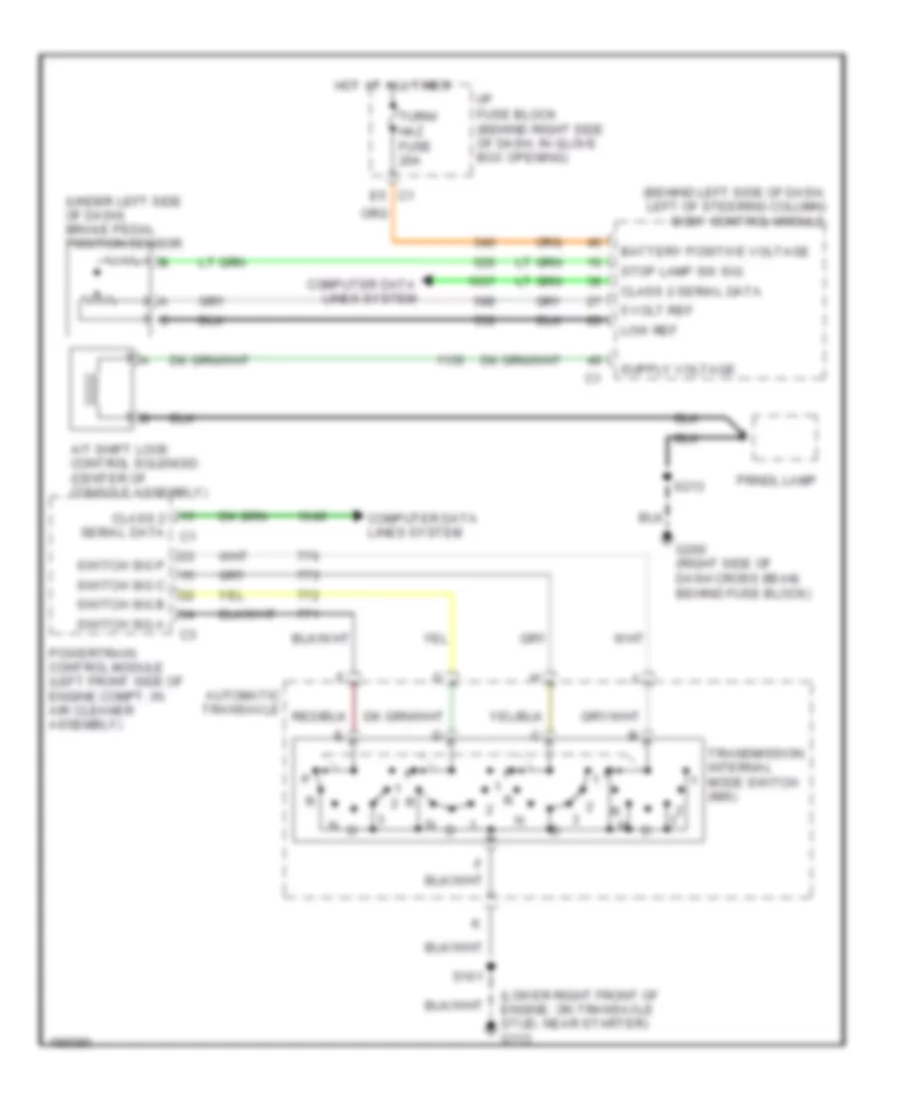
Shift Interlock Wiring Diagram for Pontiac Grand Prix GTP 2005
List of elements for Shift Interlock Wiring Diagram for Pontiac Grand Prix GTP 2005:
- (behind left side of dash, left of steering column) body control module
- (lower right front of engine, on transaxle stud, near starter) g113
- (under left side of dash) brake pedal position sensor
- 5 volt ref
- A/t shift lock control solenoid (center of console assembly)
- Automatic transaxle
- Battery positive voltage
- Class 2 serial data
- Class 2 serial data c1
- Computer data lines system
- E5 c1
- G200 (right side of dash cross beam, behind fuse block)
- Hot at all times
- I/p fuse block (behind right side of dash, in glove box opening)
- Low ref
- Powertrain control module (left front side of engine compt, in air cleaner assembly)
- Prndl lamp
- S101
- S213
- Stop lamp sw sig
- Switch sig a
- Switch sig b
- Switch sig c
- Switch sig p
- Transmission internal mode switch (ims)
- Turn/ haz fuse 20a
 English