SUPPLEMENTAL RESTRAINTS
Supplemental Restraints Wiring Diagram for Pontiac Grand Prix GTP 2005
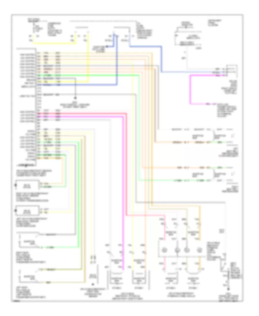
List of elements for Supplemental Restraints Wiring Diagram for Pontiac Grand Prix GTP 2005:
- A10
- A11
- A12
- A13
- A14
- A15
- A16
- A17
- A18
- Air bag indicator
- Case ground
- Class 2 serial data
- Computer data lines system
- Data link connector (dlc) (under left side of dash, right of steering column)
- G301 (inside left door sill, forward of left front seat)
- G302 (right door sill, forward of right front seat)
- Ground
- High control
- Hot in run or start
- I/p fuse block (behind right side of dash, in glove box opening)
- Ignition 1
- Inflatable restraint front end discriminating sensor
- Inflatable restraint i/p module (behind right side of dash)
- Inflatable restraint sensing & diagnostic module (sdm) (under front front seat)
- Inflatable restraint steering wheel module
- Inflatable restraint steering wheel module coil (in steering column)
- Instrument panel cluster
- L seat blt sw
- Left inflatable restraint side impact sensor (if equipped) (in driver's door)
- Left roof rail module (if equipped) (left rear of passenger compartment)
- Left seat belt pretensioner (in driver's seat)
- Logic
- Low control
- Nca
- Pnk
- Right inflatable restraint side impact sensor (if equipped) (in front passenger's door)
- Right roof rail module (if equipped) (right rear of passenger compartment)
- Right seat belt pretensioner
- Sdm class 2 serial data
- Seat belt switch (part of driver's seat belt assembly)
- Serial data
- Shorting bar
- Signal
- Sir fuse 9 10a
- Solid state
- Splice pack sp205 (right side of upper left footwell)
- Stage 1
- Stage 2
- Tan
- Underhood fuse block (mounted to right strut tower)
- Voltage
 English